
Tamper evidence means for a closure and a tamper evident closure

a technology of tamper evident and closure, which is applied in the direction of closure lids, closure stoppers, liquid dispensing, etc., can solve the problems of inability to make the interior of the closure, inability to open the closure, and considerable amount of tamper evident, so as to achieve robust and simple mold design

Active Publication Date: 2014-05-27
CREANOVA UNIVERSAL CLOSURES
View PDF31 Cites 25 Cited by
  • Summary
  • Abstract
  • Description
  • Claims
  • Application Information

AI Technical Summary

Benefits of technology

The present invention relates to a closure with a tamper evidence solution. The closure has a hinge that allows the lid to be opened and closed. The hinge has frangible elements that need to be removed to open the lid. The closure also has a double acting locking mechanism that can keep pressure above atmospheric level within a container. The technical effects of the invention are that it offers a simple mold design and a secure and easy-to-use closure that can prevent unauthorized access.

Problems solved by technology

Hinge closures in general need to be moulded in open position otherwise it would not be possible to make the interior of the closure.
For these closures a considerable amount of tamper evident means are known which are designed to lock when the closure is initially closed and are destroyed when the closure is opened for the first time.
The tamper-evident band interlocks with the lid of the closure when the closure is initially closed such that the closure can not be opened without the frangible straps being broken.
However, the known closures in general all have the disadvantages that it is not possible to use them e.g. for gaseous beverages or to re-lock them after initial opening.
A further disadvantage is that they are difficult to manufacture because they need relatively complicated moulds or have a design that results in long cycle times which avoid cost efficient production.
The inner and the outer wall area at least partly surround the locking element tightly, such that it is not possible to successfully insert any object between a wall area and the locking element.

Method used


Image

  • Tamper evidence means for a closure and a tamper evident closure
  • Tamper evidence means for a closure and a tamper evident closure
  • Tamper evidence means for a closure and a tamper evident closure

Examples


fifth embodiment

[0066]FIG. 1 through FIG. 14 are showing a first, FIG. 15 through FIG. 20 a second, FIG. 21 through FIG. 23 a third, FIG. 24 a fourth and FIG. 25 a closure 1 according to the present invention in different views and details. The embodiments mainly differ with respect to their tamper-lock features.

first embodiment

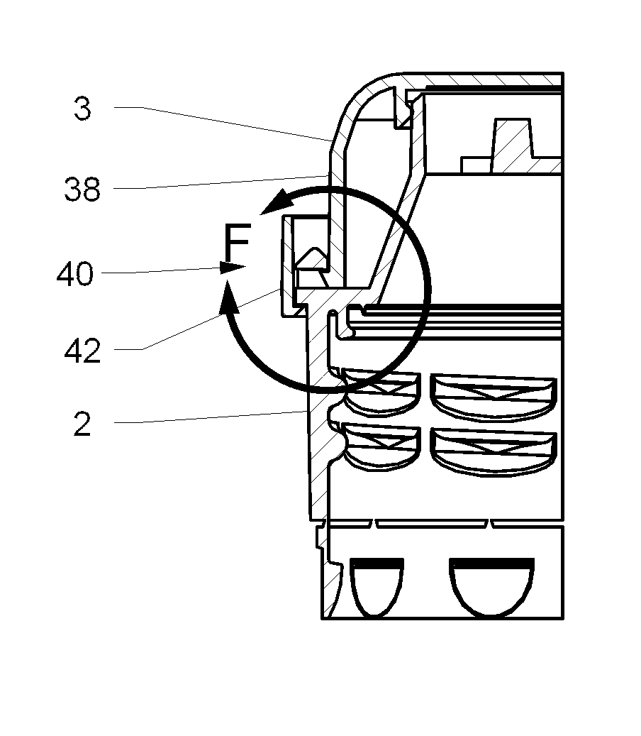
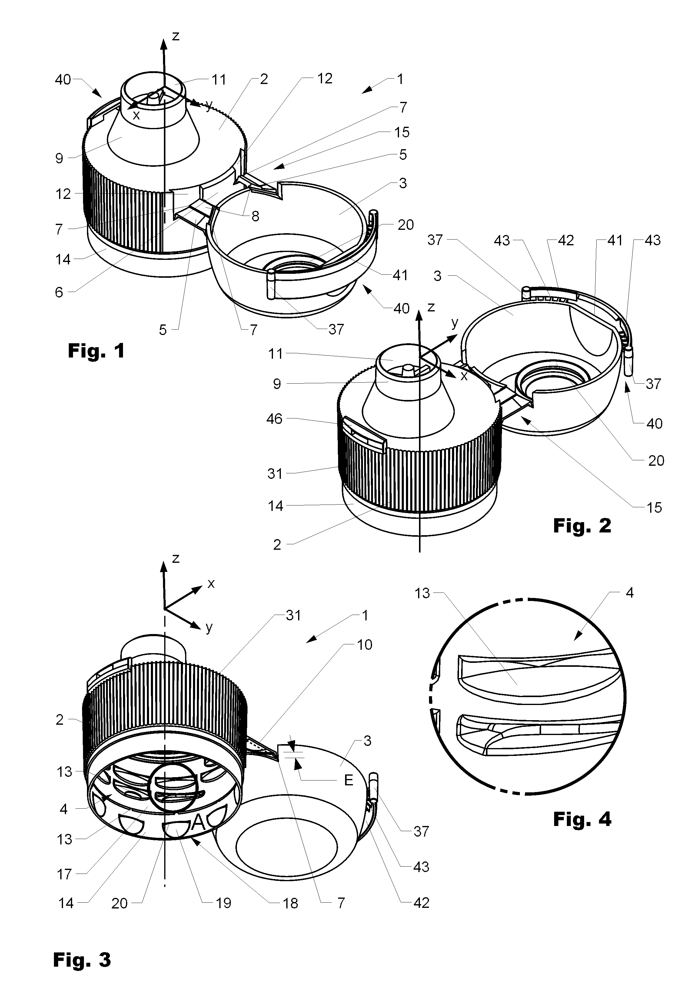
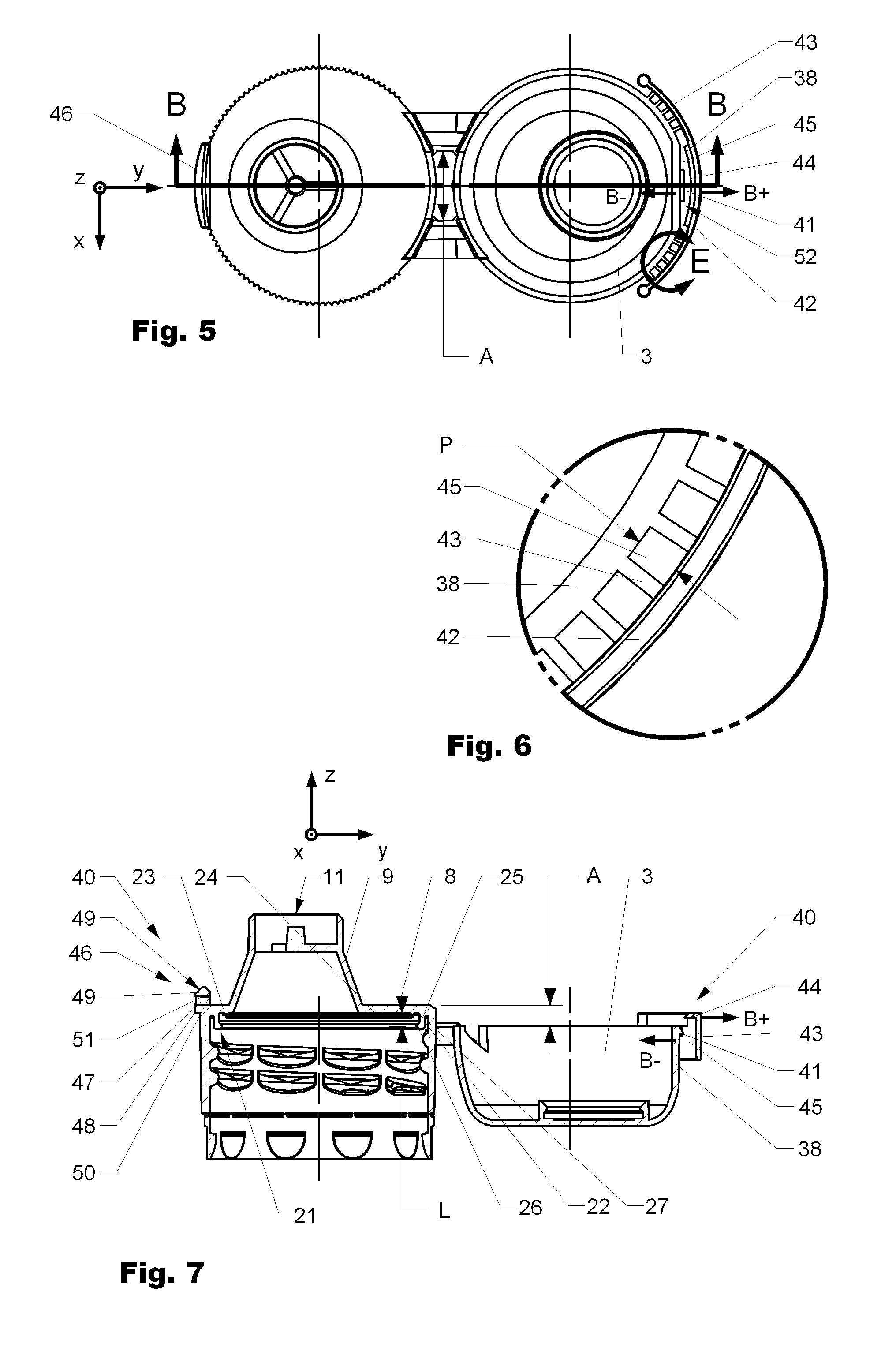
[0067]When FIG. 1 and FIG. 2 are showing closure 1 from above in a perspective back (FIG. 1) and a perspective front view (FIG. 2), FIG. 3 is showing the closure 1 in a perspective front view from below. FIG. 4 is showing detail A of FIG. 3 in a magnified manner. FIG. 5 is showing the same closure in a top view (z-direction) and FIG. 7 is showing the closure of FIG. 5 in a cross cut side view along line BB.

[0068]With respect to FIG. 1 the shown embodiments of closure 1 comprise a body 2 which is interconnected to a lid 3 by a snap hinge assembly 15. The shown snap hinge assembly 15 is very robust and has a large opening angle compared to other known hinges. In general it consists out of a pair of trapezoid elements 5 spaced a distance A (see FIG. 5) apart from each other having a gap 6 in between. Each of the trapezoid elements 5 is rotatable connected to the lid 3 and the body 2 by hinges 7, preferably film hinges (thin web of material) having a rotating axis. The hinges 7 of each ...

second embodiment

[0085]FIGS. 14 through 15 are showing a closure 1 with a locking mechanism 40 according to the present invention. FIG. 14 is showing the closure 1 in an open position and FIG. 15 is showing the same closure in a closed position. FIG. 16 is showing the closure 1 according to FIGS. 14 and 15 in an open position in a back view and FIG. 18 the same closure in a closed position in a front view. FIG. 17 (open position) and FIG. 19 (closed position) are showing the cross-cuts through the closures according to FIGS. 16 and 18 along cutting-lines GG and HH.

[0086]In difference to the closure according to FIGS. 1 to 13 the locking element 46 is arranged in closed position in general above the main deck 8 of the body 2 and with respect to the hinge assembly 15 on the opposite side of the orifice 9. An advantage of this arrangement is that the tamper evident means / locking mechanism 40 is, as it can be seen in FIGS. 15 and 19, fully integratable in the outer contour of the closure 1.

[0087]FIG. 19...


PUM


Abstract

The invention concerns a tamper evidence and locking means for a closure and a tamper evident closure. The tamper evidence and locking means indicate initial opening and allow relocking the closure after initial opening.

Description

CROSS REFERENCE TO RELATED APPLICATION[0001]The present application is a 35 U.S.C. §371 national phase conversion of PCT / EP2005 / 054307 filed 1 Sep. 2005, which claims priority of U.S. Provisional Patent Application No. 60 / 606,240 filed 1 Sep. 2004, U.S. Provisional Patent Application No. 60 / 655,324 filed 23 Feb. 2005 and PCT / EP2005 / 051575 filed 8 Apr. 2005, which are herein incorporated by reference. The PCT International Application was published in the English Language.BACKGROUND OF THE INVENTION[0002]1. Field of the Invention[0003]The invention relates to a tamper evidence means for a closure, respectively to a tamper evident closure. In particular the invention provides a hinged tamper evident cap for glass or PET containers with contents such as beverages at, above or below atmospheric pressure or having gaseous components.[0004]2. Description of the Art[0005]Various hinged closures for drinks packages are known from prior art which comprise features foreseen to indicate initia...

Claims


Application Information

Patent Timeline
Patent Type & Authority Patents(United States)
IPC IPC(8): B65D41/34B65D43/16
CPCB65D47/0809B65D2215/02B65D2101/0023B65D2251/105B65D47/243B65D2401/15
Inventor DRUITT, RODLAGLER, LOUIS
Owner CREANOVA UNIVERSAL CLOSURES
Learn More