
System and method for using diagnostic pulses in connection with defibrillation therapy

a technology of diagnostic pulses and pulses, which is applied in the field of defibrillator systems, can solve the problems of reducing the amount of blood pumped to the body, affecting the normal or sinus heartbeat rhythm, and ineffective pumping of the ventricular muscles, so as to enhance the patient's responsiveness to defibrillation therapy, determine the effectiveness of defibrillation therapy, and quickly restore perfusion

Active Publication Date: 2014-05-20
PHYSIO CONTROL INC
View PDF12 Cites 38 Cited by
  • Summary
  • Abstract
  • Description
  • Claims
  • Application Information

AI Technical Summary

Benefits of technology

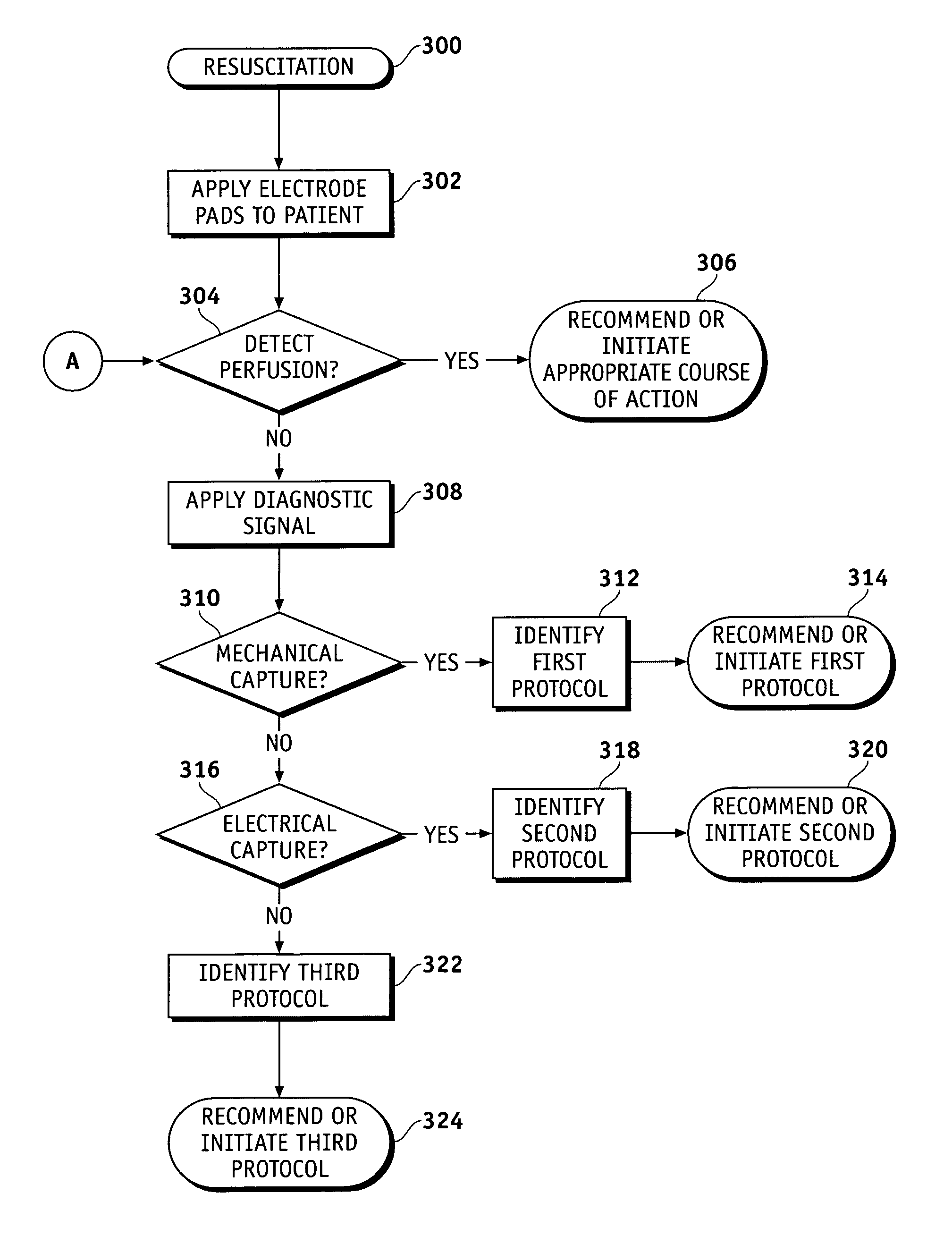
The patent describes a system and method for determining the effectiveness of defibrillation therapy for a patient by using a diagnostic signal before or after the therapy. This diagnostic signal can include electrical pulses designed to elicit a physiologic response from the patient, such as a detectable response from the heart. The system can recommend or initiate different therapy protocols based on the detected patient response, such as CPR, ventilation, or drugs which enhance the patient's responsiveness to defibrillation therapy. The techniques described in the patent are quick, noninvasive, and simple to implement in existing defibrillation and monitoring devices. The method involves applying a diagnostic signal, detecting a current physiologic response, and identifying a resuscitation protocol based on that response. This information helps to determine the likelihood of successful defibrillation therapy or continued application of stimulus pulses.

Problems solved by technology

In certain circumstances, the normal or sinus heartbeat rhythm may be adversely affected as a result of some type of malfunction in the heart's electrical control system.
When this type of malfunction occurs, an irregular heartbeat may result, causing the ventricular muscles to pump ineffectively, thus reducing the amount of blood pumped to the body.
In this event, the ventricular muscles are not able to pump blood out of the heart, and there is no initiation of a coordinated heartbeat, leading to death within minutes.
VF rarely terminates spontaneously, and its unpredictability exacerbates the clinical problem of treating patients in sudden cardiac arrest.
These latter techniques are only able to make predictions based on statistical correlations between characteristics of the electrocardiogram (“ECG”) signal and the probability of successful defibrillation in a population exhibiting similar measurements.
As such, the predictions can be inaccurate and the results can be corrupted by artifact.

Method used


Image

  • System and method for using diagnostic pulses in connection with defibrillation therapy
  • System and method for using diagnostic pulses in connection with defibrillation therapy
  • System and method for using diagnostic pulses in connection with defibrillation therapy

Examples


Embodiment Construction

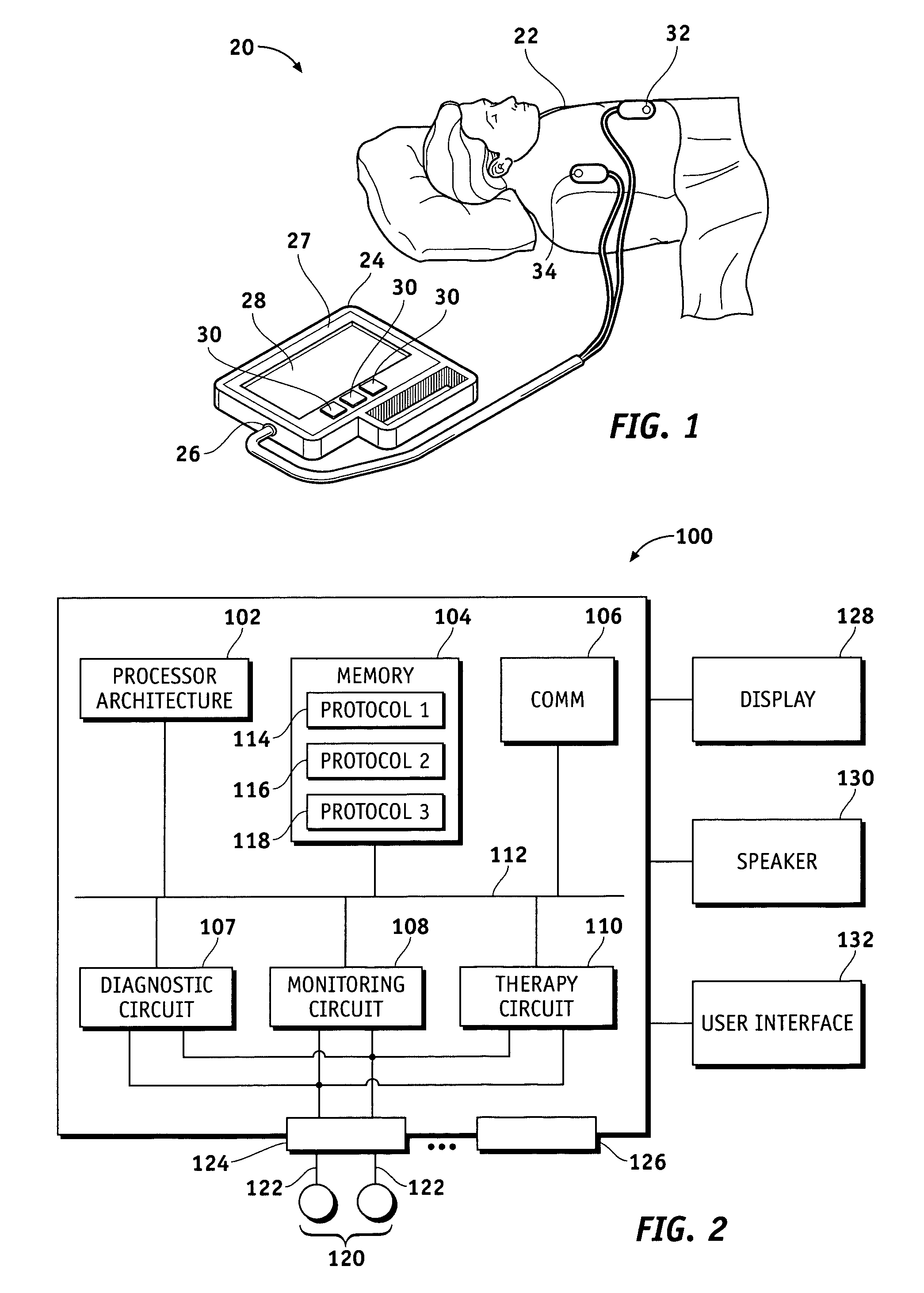
[0016]The following detailed description is merely exemplary in nature and is not intended to limit the invention or the application and uses of the invention. For example, a practical embodiment of the invention may be deployed in connection with an automatic or automated external defibrillator, a semi-automatic or semi-automated external defibrillator, a manual external defibrillator, patient monitoring systems, and possibly implantable defibrillator devices. Furthermore, there is no intention to be bound by any expressed or implied theory presented in the preceding technical field, background, brief summary or the following detailed description.

[0017]The invention may be described herein in terms of functional and / or logical block components and various processing steps. It should be appreciated that such block components may be realized by any number of hardware, software, and / or firmware components configured to perform the specified functions. For example, an embodiment of the...


PUM


Abstract

An external defibrillator system is disclosed that generates and applies a diagnostic signal to the patient in conjunction with defibrillation therapy. The diagnostic signal is designed to elicit a physiologic response from the patient's heart, namely, mechanical cardiac response and electrical cardiac response, electrical cardiac response only, or no cardiac response. Depending upon the type of cardiac response detected, the system selects an appropriate resuscitation protocol that considers the likely responsiveness of the patient to defibrillation therapy. In one practical embodiment, a stimulus signal is applied to patients that show mechanical and electrical capture in response to the diagnostic signal. The stimulus signal maintains the mechanical capture (and, therefore, perfusion) for a period of time prior to the delivery of a defibrillation pulse.

Description

TECHNICAL FIELD[0001]The present invention relates generally to defibrillator systems. More particularly, the present invention relates to a defibrillator system that applies diagnostic electrical pulses to the patient during a resuscitation event to determine a recommended treatment protocol.BACKGROUND[0002]A normal human heart pumping pattern is called a sinus rhythm, and the pattern is regulated by the body's biological pacemaker within the upper right chamber of the heart, which is commonly referred to as the right atrium. This natural pacemaker, which is generally referred to as the sinoatrial (“SA”) node, sends electrical signals to the right and left ventricular muscles in the lower chambers of the heart. The ventricular muscles then implement the pumping action under the control of the SA node. The right ventricular muscle pumps blood to the lungs for oxygenation, and the left ventricular muscle pumps the oxygenated blood to various parts of the body.[0003]In certain circums...

Claims


Application Information

Patent Timeline
Patent Type & Authority Patents(United States)
IPC IPC(8): A61N1/38A61N1/39
CPCA61N1/385A61N1/39A61N1/3925A61N1/3962A61N1/3987A61N1/39044A61H31/005A61H2031/002A61M5/1723A61M2230/005A61M2230/04A61N1/025
Inventor HAMPTON, DAVID R.BANVILLE, ISABELLE
Owner PHYSIO CONTROL INC
Learn More