
Device for tensioning a flexible band

a flexible band and device technology, applied in the field of devices for tensioning flexible bands, can solve the problems of no manual feedback of tension, no device present drawbacks, ancillary devices, etc., and achieve the effects of simple adjustment possibilities, improved sensitivity to the degree of tensioning, and improved flexibility

Active Publication Date: 2014-05-20
IMPLANET SA
View PDF5 Cites 25 Cited by
  • Summary
  • Abstract
  • Description
  • Claims
  • Application Information

AI Technical Summary

Benefits of technology

[0015]The present invention aims to provide a device for tensioning a flexible band that provides a better response than those previously known to the requirements of the practice, notably in that it will allow for a much greater flexibility, a better sensitivity to the degree of tensioning because of the very design of the tools used for such a tensioning, and in that it presents much improved and simple adjustment possibilities.
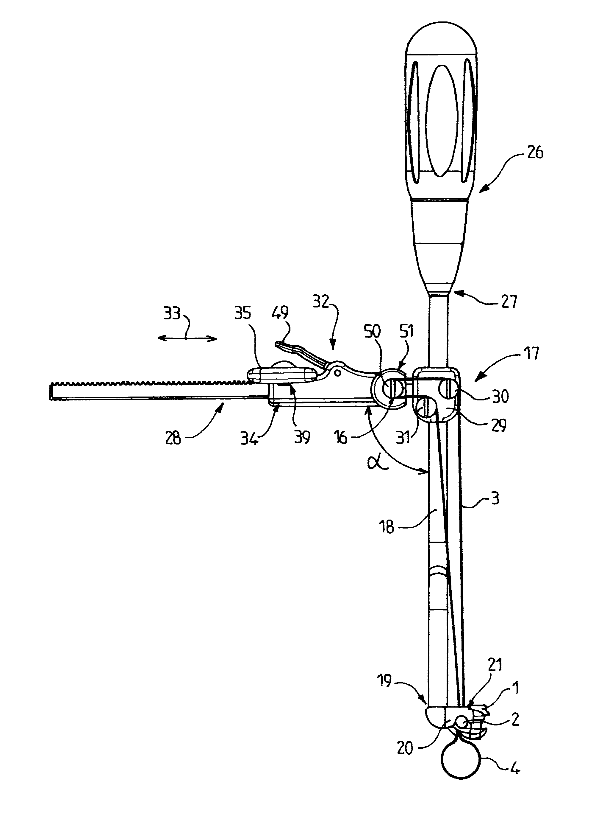
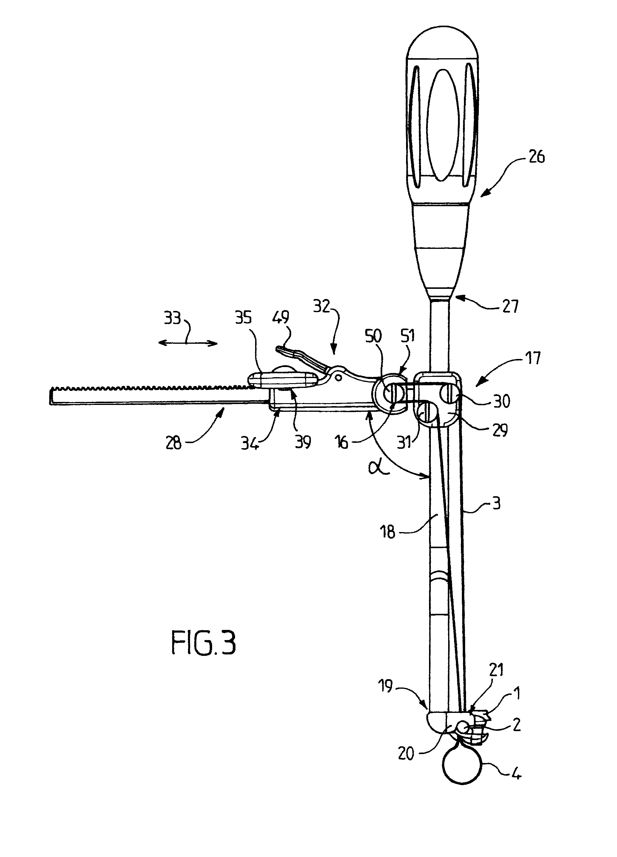
[0017]The manual screwing means for actuating the mobile part which is itself offset on a lateral branch forming an angle, allow for a gradual and controlled tensioning of the flexible strip.
[0020]The actuation key allows for a good manual tightening sensitivity;
[0021]the ratchet system comprises a lever arm for releasing the ratchet. It is therefore very easy to release the tension, for example to allow for a new adjustment;

Problems solved by technology

However, such devices present drawbacks because they are aggressive.
Such an ancillary does, however, present drawbacks.
Furthermore, no manual feedback of the tension is possible with such an instrument which thus requires, to avoid crushing the bony element, an adjustable dynamometric system making it possible to stop the tensioning beyond a certain determined value.

Method used


Image

  • Device for tensioning a flexible band
  • Device for tensioning a flexible band
  • Device for tensioning a flexible band

Examples


Embodiment Construction

[0035]Hereinafter in the description, the same reference numbers will be used to designate the same elements.

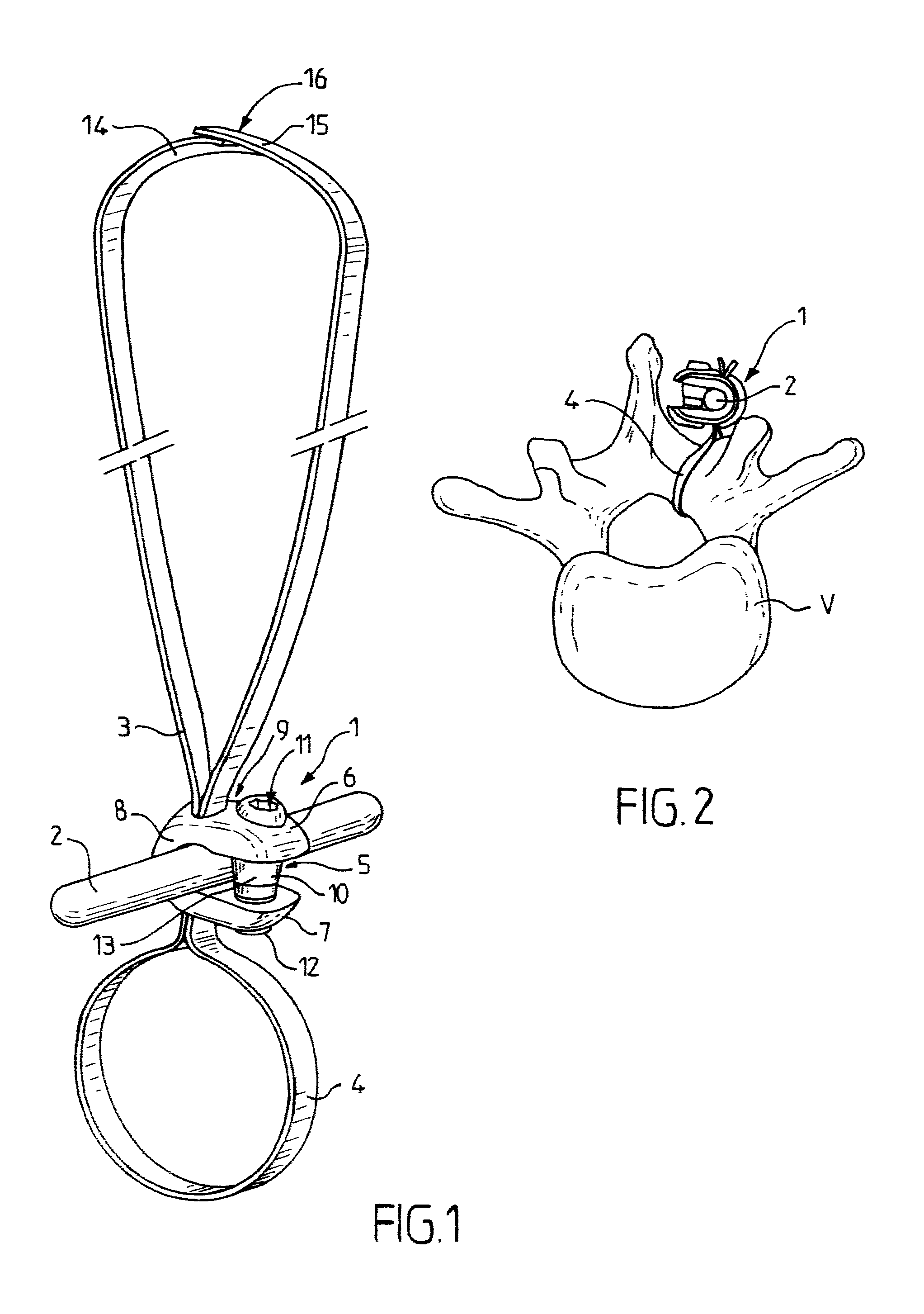
[0036]FIG. 1 shows an embodiment of a fixing body 1 on a cylindrical rod 2 and a flexible strip 3 made of braided polymer, for example polyester, 6 mm wide and 30 cm long to form the loop 4.

[0037]Adjustable means 5 for blocking the flexible strip on the fixing body 3 are provided. The fixing body 1 is, for example, formed by a part which is all one piece forming a clamp having U-shaped cross section, said U comprising two thick branches 6, 7 with a substantially demi-oval shaped cross section, symmetrical relative to a longitudinal plane and linked together by a link part 8 in the form of a half toroidal ring forming, on one side, the demicylindrical bottom of the U and, on the other side, the rounded outer walls of the branches 6 and 7.

[0038]The bottom wall of the U is of a shape complementing that of the rod 2, or substantially complementing same.

[0039]Each branch 6, 7 incl...


PUM


Abstract

A device (17) is provided for tensioning a flexible band (3) used to maintain a bone element on an implant. The device includes a rod (18) having a first end (19) provided with means (20) for bearing on the implant, a movable part (32) for hooking the flexible band onto a portion (28) of the device, and means (34) for adjustably locking the movable part in translation in relation to the portion of the device. The rod (18) includes a gripping handle (26) at the second end (27) thereof. The aforementioned portion of the device forms an angle α with the rod (18) to which it is rigidly connected at an intermediary point, the direction of the band being altered at an angle, and the aforementioned adjustable locking means (34) includes manual screwing means (35) for actuating the movable part.

Description

CROSS REFERENCE TO RELATED APPLICATION[0001]This application is a continuation of co-pending International Application No. PCT / FR2011 / 000639, filed Dec. 6, 2011, the contents of which are hereby incorporated by reference in their entirety.BACKGROUND OF THE INVENTION[0002]The present invention relates to a device for tensioning a flexible strip for securing a bony element to an implant, comprising a rod having a first end provided with means for bearing on the implant, a mobile part for attaching the flexible strip to a portion of the device and adjustable means for blocking the part that is mobile in translation relative to said portion of the device.[0003]It is particularly importantly applicable, although not exclusively applicable, to the field of the straightening of the spinal column of a patient having abnormal curvature.[0004]In this case, with the vertebrae not being correctly aligned relative to one another in relation to the vertebral axis, they exhibit mutual inclinations...

Claims


Application Information

Patent Timeline
Patent Type & Authority Patents(United States)
IPC IPC(8): A61B17/88A61B17/70
CPCB25B25/00A61B17/7074A61B17/7083A61B17/7053A61B17/8869A61B17/7076A61B17/8861A61B17/8841A61B17/82A61B17/88
Inventor BACCELLI, CHRISTIANLE COUEDIC, REGIS
Owner IMPLANET SA
Learn More