Air-supplied dry cooler

a dry cooler and air technology, applied in the direction of heat exchanger types, stationary conduit assemblies, steam/vapor condensers, etc., can solve the problems of condensate freezing, quick freezing of generated condensate, and possible problems, so as to reduce the number of weld seams, and reduce the risk of leakage

Inactive Publication Date: 2014-05-20
GEA ENERGIETECHNIK GMBH
View PDF43 Cites 1 Cited by
  • Summary
  • Abstract
  • Description
  • Claims
  • Application Information

AI Technical Summary

Benefits of technology

The invention is a dry cooler for a power plant that optimizes the construction of the suction chamber and reduces the risk of leakage and time-consuming weld seams. The design uses a cross-sectional wedge-shaped design and a single suction chamber with a single central suction, which reduces the number of weld seams and the risk of leakage. The cross-sectional area of the baffle openings is matched to the cross-sectional area of the suction pipe, which simplifies the design. The invention also includes a seal between the heat exchanger pipes and the pipe bottom using a weld seam bump, which prevents pressure fluctuations and freezing during continuous operation. Overall, the invention improves the safety and efficiency of the dry cooler.

Problems solved by technology

However, problems may arise in certain situations when larger quantities of the condensate accumulate in the suction chamber at low temperatures.
The large quantities of condensate can cause supercooling and in extreme situations even freezing of the condensate.
This danger exists at outside temperatures below freezing, both during operation and during startup, because the large quantity of frozen condensate located just below the baffle opening may not be thawed quickly enough by the gas-steam mixture, so that the newly generated condensate quickly freezes and may in extreme situations block the baffle openings.
Another problem can arise when large quantities of condensate accumulate in the suction chamber, which must be returned to the dephlegmator pipes through the same opening through which the gas-steam mixture enters the suction chamber.
This may cause undesirable pressure variations inside the individual dephlegmator pipes.

Method used


Image

  • Air-supplied dry cooler
  • Air-supplied dry cooler
  • Air-supplied dry cooler

Examples


Embodiment Construction

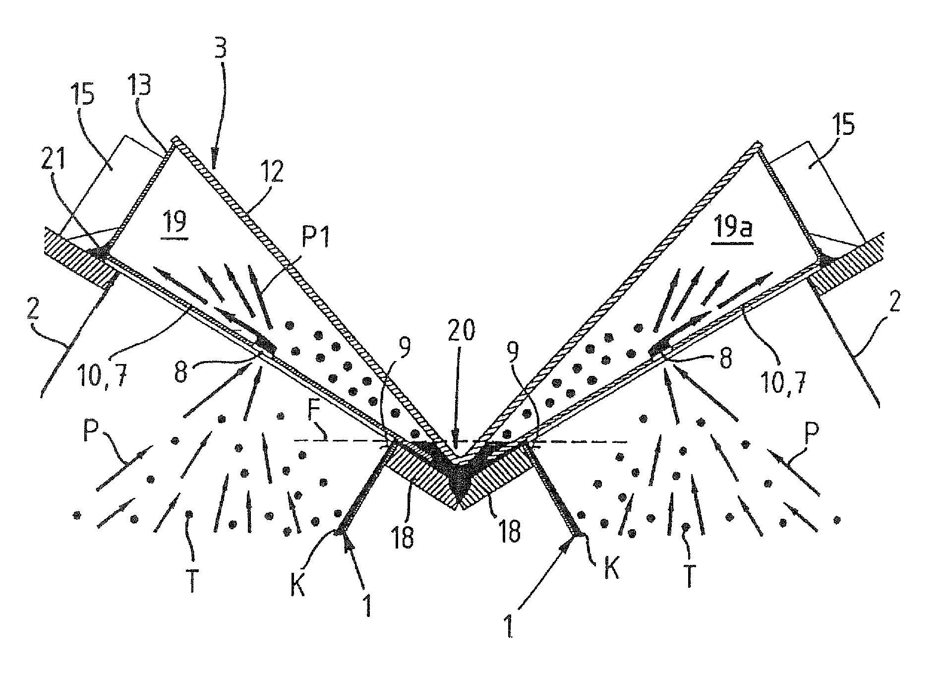
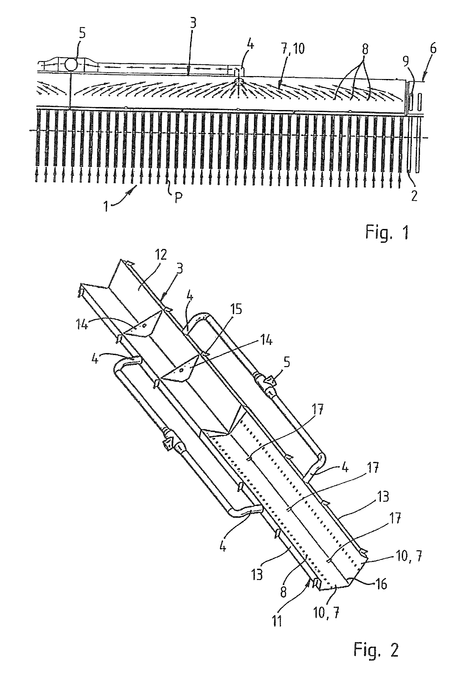
[0029]FIG. 1 shows the upper region of the direct-flow condenser (dephlegmator) 1 of an air-supplied dry cooler, which is not illustrated in its entirety, for condensing steam. The flow direction of the vapor is indicated by the arrows P. The steam rises inside heat exchanger pipes 2 arranged in parallel and enters a suction chamber 3. A suction pipe 4, through which the steam-gas mixture is suctioned off the dephlegmator 1, is connected at the center of the suction chamber 3. As depicted in the perspective diagram of FIG. 2, two respective suction chambers 3 are each connected to a central suction 5.

[0030]FIG. 1 further shows on the rightmost side of the Figure a portion of a direct-flow condenser 6. The direct-flow condenser 6 is not provided with a suction chamber 4, because the steam flows downward from the top. However, the heat exchanger pipes 2 have the same cross-section as the heat exchanger pipes of the dephlegmator 1. As clearly indicated, the suction chamber 3 has signif...


PUM


Abstract

An air-supplied dry cooler for the condensation of water vapor includes at least one direct-flow condenser and at least one counter-flow condenser (dephlegmator), wherein heat exchanger pipes of the counter-flow condenser are connected to an upper suction chamber, and wherein a cover reducing the discharge cross-section of at least one heat exchanger pipe is provided with cover orifices. The sum of the cross-sectional surfaces of the cover orifices corresponds to no more than the cross-sectional surface of a suction pipe connection to the suction chamber.

Description

CROSS-REFERENCES TO RELATED APPLICATIONS[0001]This application is the U.S. National Stage of International Application No. PCT / DE2008 / 001325, filed Aug. 12, 2008, which designates the United States and has been published as International Publication No. WO 2009 / 036719 and which claims the priority of German Patent Application, Serial No. 10 2007 044 658.8, filed Sep. 18, 2007, pursuant to 35 U.S.C. 119(a)-(d).BACKGROUND OF THE INVENTION[0002]The invention relates to an air-supplied dry cooler for condensing steam.[0003]It is known to use air for condensing turbine steam. With direct air-cooled condensation, the turbine steam is condensed in ribbed pipe elements (surface condensers) connected in parallel, and the condensate is returned to the feed water loop. The interior of the ribbed pipe elements is under vacuum, with the non-condensable gases being suctioned off. The cooling air flow is generally produced with fans, rarely by natural airflow. Dry coolers with a roof structure (A-...

Claims


Application Information

Patent Timeline
Patent Type & Authority Patents(United States)
IPC IPC(8): F28B3/00
CPCF28B9/08F28B1/06
Inventor SCHMIDT, MARKUS
Owner GEA ENERGIETECHNIK GMBH
Why Eureka
Try Eureka