System for obtaining information in vehicle
a vehicle and information technology, applied in the field of vehicle information systems, can solve the problems of troublesome transportation of automobiles to particular facilities, inability to go to particular facilities under its own power, and difficulty in moving automobiles to facilities, so as to ensure the credibility of information to be obtained and obtain information. the effect of easy operation
- Summary
- Abstract
- Description
- Claims
- Application Information
AI Technical Summary
Benefits of technology
Problems solved by technology
Method used
Image
Examples
embodiment 1
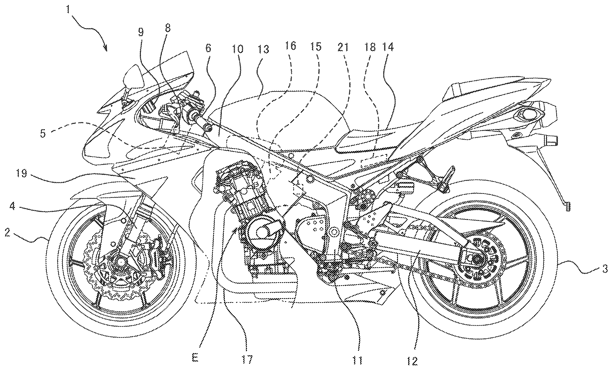
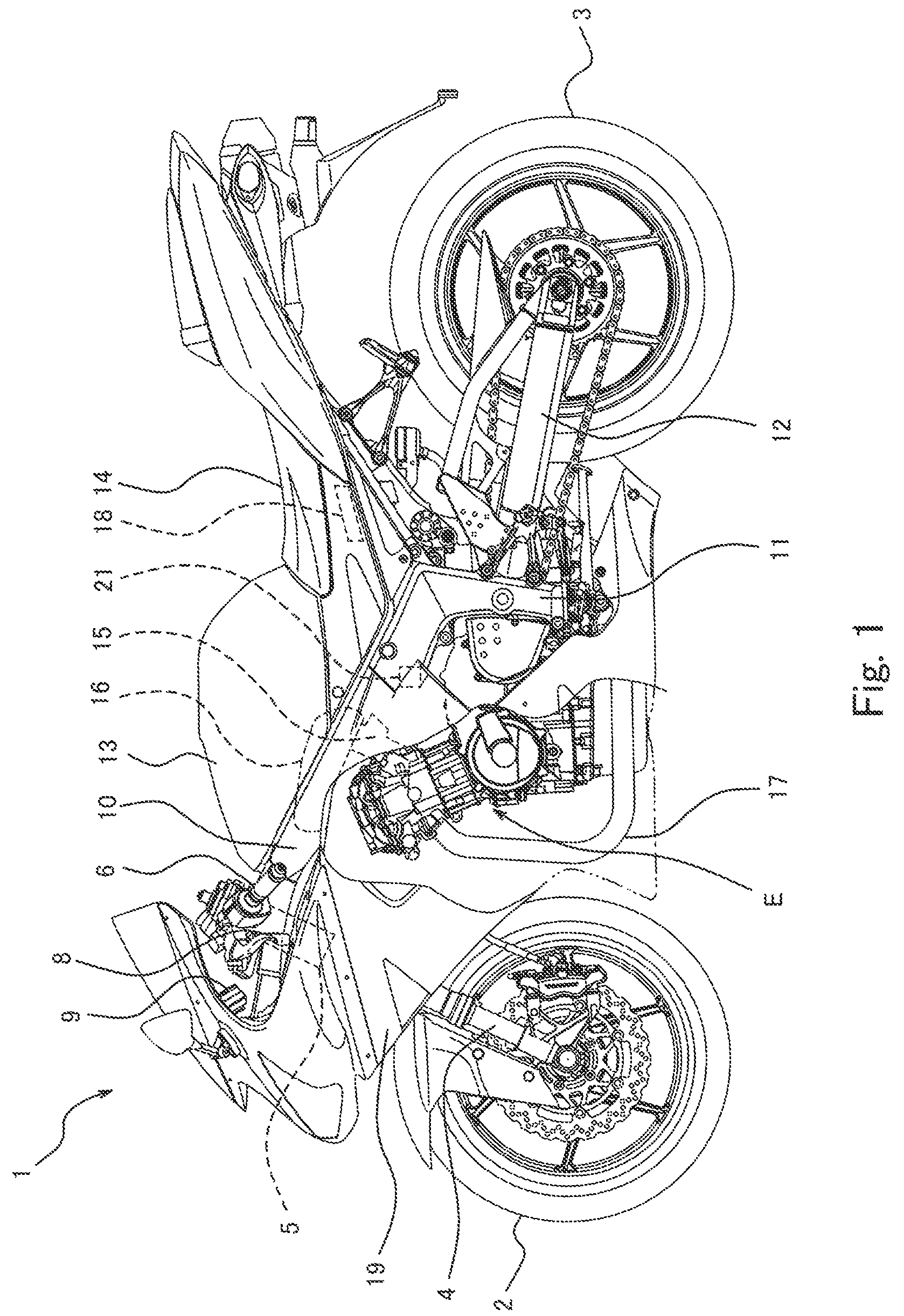
[0038]FIG. 1 is a left side view of a motorcycle 1 (vehicle) according to Embodiment 1 of the present invention. As shown in FIG. 1, the motorcycle 1 includes a front wheel 2 and a rear wheel 3. The front wheel 2 is rotatably mounted to lower end portions of a pair of right and left front forks 4 extending substantially vertically. Upper portions of the right and left front forks 4 are coupled together via a pair of upper and lower brackets (not shown), and are rotatably supported by a head pipe 5 provided on the vehicle body. A bar-type steering handle 6 extending in a rightward and leftward direction is attached to the upper bracket. The driver rotates the steering handle 6 to turn the front wheel 2 around the steering shaft.
[0039]A right grip of the steering handle 6 which can be gripped by the driver's right hand is a throttle grip (not shown). The driver rotates the throttle grip by twisting the driver's wrist to adjust a driving speed. A clutch lever 8 is attached to the steer...
embodiment 2
[0100]Next, Embodiment 2 will be described. In Embodiment 2, an EDR 120 (ECU 118) is configured in such a manner that a trigger generating section 131 sends a trigger to a data output control section 132 if it is determined that the motorcycle 1 has fallen and a rear wheel speed is equal to or greater than a predetermined value. The other configuration is identical to that of Embodiment 1 and the same components are identified by the same reference symbols and will not be described in repetition.
Event Data Recorder
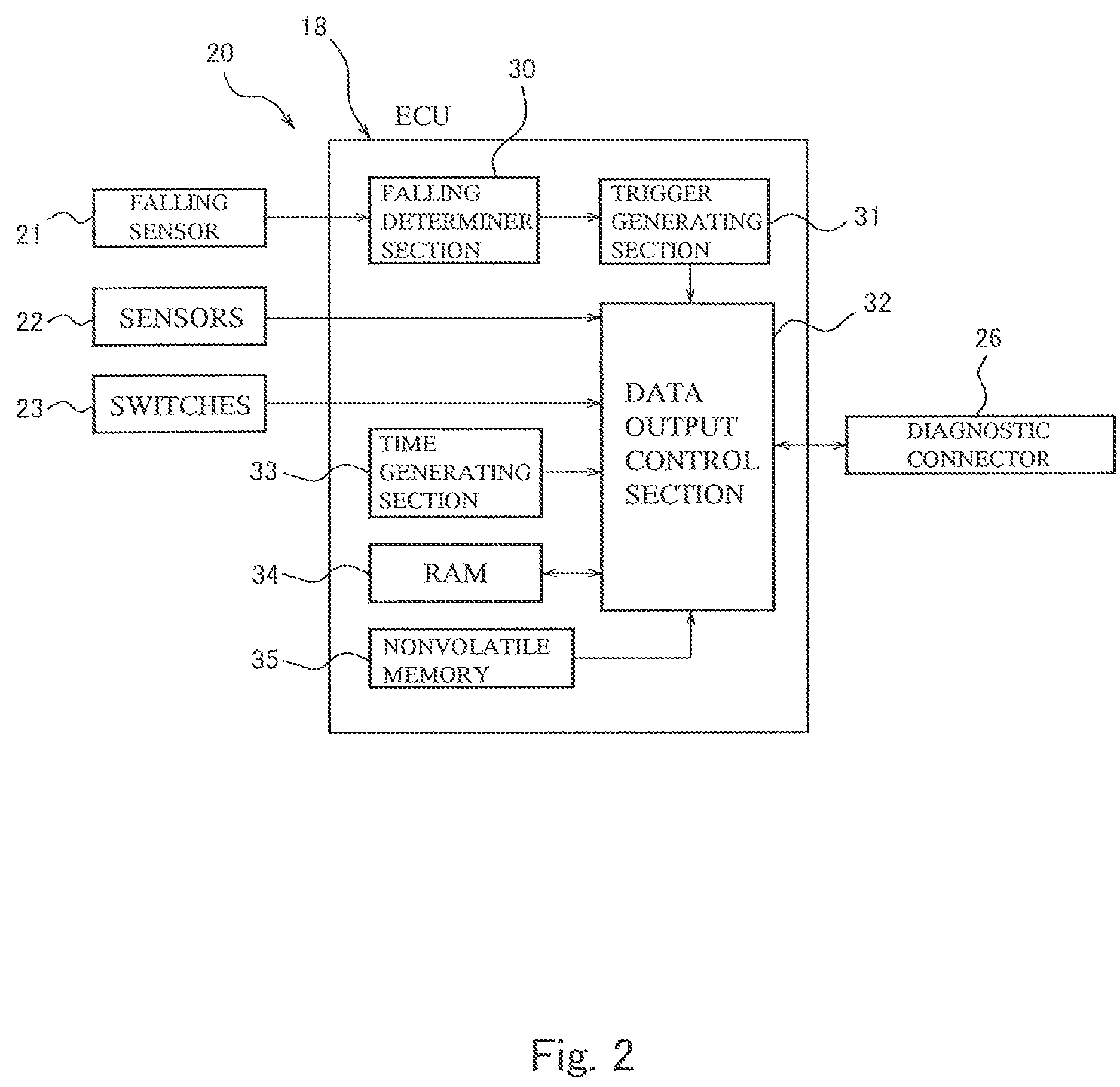
[0101]FIG. 8 is a block diagram showing the EDR 120 according to Embodiment 2 of the present invention. Like the EDR 20 of Embodiment 1, the EDR 120 is configured by utilizing a processor function of the ECU 118. The ECU 118 is coupled with the falling sensor 21, the sensors 22 (devices), the switches 23 (devices), a front wheel speed sensor 24 (device) for detecting a front wheel speed from a rotational speed of the front wheel 2, and a rear wheel speed sensor 25 (device)...
embodiment 3
[0117]Next, Embodiment 3 will be described. The event data recorder 120 is activated when a slip ratio of the front wheel 2 or the rear wheel 3 of the motorcycle 1 increases to a value equal to or greater than a predetermined value and it is determined (estimated) that the motorcycle 1 is more likely to fall. The other configuration is identical to that of Embodiment 2 and the same components are identified by the same reference symbols and will not be described in repetition.
[0118]Although not shown, in the event data recorder 120 incorporated into the motorcycle 1 of Embodiment 3, the front wheel speed sensor 24 and the rear wheel speed sensor 25 are coupled to the falling determiner section 30 in the ECU 118. The falling determiner section 30 in the ECU 118 is configured to determine (estimate) that the front wheel 2 or the rear wheel 3 is locked or spinning and therefore the motorcycle 1 is going to fall, when a difference between the front wheel speed detected by the front whee...
PUM
 Abstract
Description
Claims
Application Information
 - R&D
- Intellectual Property
- Life Sciences
- Materials
- Tech Scout
- Unparalleled Data Quality
- Higher Quality Content
- 60% Fewer Hallucinations
Browse by: Latest US Patents, China's latest patents, Technical Efficacy Thesaurus, Application Domain, Technology Topic, Popular Technical Reports.
© 2025 PatSnap. All rights reserved.Legal|Privacy policy|Modern Slavery Act Transparency Statement|Sitemap|About US| Contact US: help@patsnap.com


