
Base fabric for air bag, method of producing the same and air bag

a technology of air bags and base fabrics, applied in weaving, pedestrian/occupant safety arrangements, vehicular safety arrangements, etc., can solve the problems of air bag stowability, air bag weight increase, air bag stowability, etc., to achieve air bag spread, air shieldability, heat resistance and flame retardancy, the effect of promoting the spread of air bags

Active Publication Date: 2014-05-13
SEIREN CO LTD
View PDF19 Cites 0 Cited by
  • Summary
  • Abstract
  • Description
  • Claims
  • Application Information

AI Technical Summary

Benefits of technology

The present invention provides a base fabric for an air bag that is light-weight, flexible, and satisfies high stowability, air shieldability, heat resistance, and flame retardancy. The fabric has a good adhesion with a resin coating and is difficult to undergo stitch dislocation and fray. The invention also provides a method for producing the base fabric and an air bag using the fabric. The use of a light-weight and flexible base fabric for air bag can contribute to promoting the spread of air bag, reducing fuel consumption in automobiles, and protecting the environment.

Problems solved by technology

However, the fabric becomes hard when coated and hence becomes difficult to be folded compactly, thus giving rise to a problem in point of stowability of the air bag.
Moreover, for satisfying all of high heat resistance, flame retardancy and air shieldability, it is necessary that the amount of the heat-resistant elastomer applied per unit area of the fabric be 50 g / m2 or more, thus giving rise to the problem that the weight of the air bag increases.
In this air bag, although the stowability thereof is improved, the adhesion between the resin coating and the fabric cannot be considered sufficient.
Further, in the case where the amount of the elastomer applied is as small as 20 g / m2 or less, it is difficult to satisfy the flame retardancy based on the resin coating, in such a localized state of the resin.
According to this fabric, although the stowability of the air bag and the adhesion between the resin coating and the fabric are improved, it cannot help being considered that the fabric is insufficient in point of flame retardancy based on the resin coating.

Method used


Image

  • Base fabric for air bag, method of producing the same and air bag

Examples


example 1

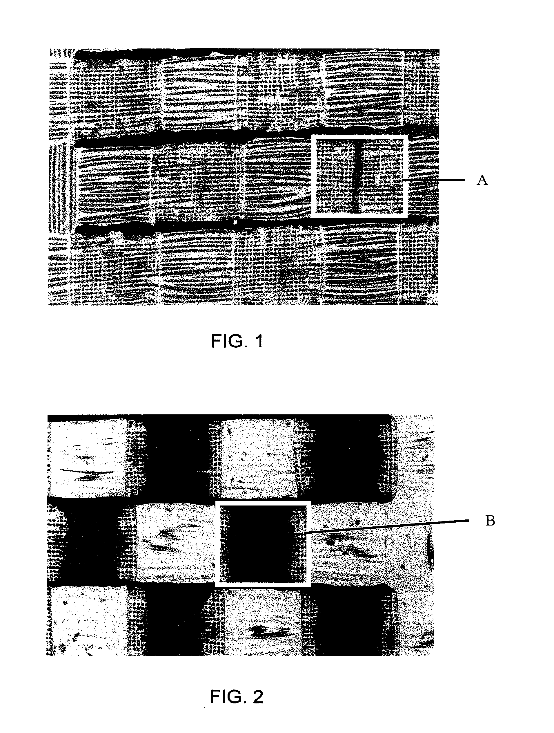
[0039]Yarns of 470 dtex / 72 filaments of nylon 66 fiber having a circular section were used as warp and weft and subjected to weaving. There was obtained a plain weave fabric having a warp weave density of 46 pc. / 2.54 cm and a like weft weave density. This fabric was then subjected to scouring and heat setting by a conventional method so that the warp weave density and the weft weave density were each kept at 46 pc. / 2.54 cm. Next, using a solventless type silicone resin with a viscosity of 15,000 mPa·s and using a stainless steel knife having an edge thickness of 0.1 mm at a portion of contact with the fabric and a urethane bed, the knife was pushed against the fabric at a sandwiching force of 2.5 N / cm to effect coating. Thereafter, heat treatment was performed at 180° C. for 60 seconds with use of a pin tenter dryer to afford a base fabric for an air bag having an applied resin quantity of 12 g / m2. In an intertwined portion interface as a warp-weft crossing portion, the area ratio o...

example 2

[0040]Using the same fabric as that having gone through weaving, scouring and heat setting in Example 1, coating was performed under the same conditions as in Example 1 except that there was used a stainless steel knife having an edge thickness at the contact portion of 0.2 mm and that the sandwiching force was set at 0.6 N / cm. Subsequent heat treatment was conducted also under the same conditions as in Example 1.

[0041]The air bag base fabric thus obtained was found to have an applied resin quantity of 18 g / m2 and an area ratio of the resin of 100% in the warp-weft crossing intertwined portion interface. The air bag base fabric proved to be superior in all of flame retardancy, slip-off resistance, flexibility and air shieldability.

example 3

[0042]Yarns of 470 dtex / 72 filaments of nylon 66 fiber having a circular section were used as warp and weft and subjected to weaving. There was obtained a plain fabric having a warp weave density of 53 pc. / 2.54 cm and a like weft weave density. This fabric was then subjected to heat setting so that the warp weave density and the weft weave density were each kept at 53 pc. / 2.54 cm. Next, using a solventless type silicone resin with a density of 15,000 mPa·s and using a stainless steel knife having an edge thickness of 0.1 mm at a portion of contact with the fabric and a urethane bed, the knife was pushed against the fabric at a sandwiching force of 2.5 N / cm to effect coating. Thereafter, heat treatment was performed at 180° C. for 60 seconds with use of a pin tenter dryer to afford a base fabric for an air bag having an applied resin quantity of 15 g / m2. In an intertwined portion interface as a warp-weft crossing portion, the area ratio of resin was 89% and the fabric was superior in...


PUM

PropertyMeasurementUnit
thicknessaaaaaaaaaa
thicknessaaaaaaaaaa
thicknessaaaaaaaaaa

Abstract

A base fabric for an air bag is provided which is light-weight, flexible, superior in stowability, air shieldability, heat resistance and flame retardancy, further superior in the adhesion to resin and difficult to undergo stitch dislocation and fray. The air bag base fabric comprises a synthetic fiber fabric at least one surface of which is coated with resin. The resin is present also over at least 85% of the total area of an intertwined portion interface as a warp-weft crossing portion of the synthetic fiber fabric.

Description

[0001]This application is a U.S. National Phase under 35 U.S.C. §371 of International Application No. PCT / JP2007 / 066828, filed Aug. 23, 2007.[0002]The present invention relates to an air bag attached to a vehicle and adapted to swell in an instant upon occurrence of a collision accident of the vehicle to protect the passenger concerned. More particularly, the present invention relates to an air bag using a resin-coated fabric and superior in all of flame retardancy, light-weightness, texture and stowability.BACKGROUND OF THE INVENTION[0003]Recently there have been developed various air bag devices for ensuring the safety of a passenger upon occurrence of an accident of traffic means, especially an automobile, and the usefulness thereof has been recognized. Consequently, air bag devices have come to be attached in a very high rate to automobiles. Such air bag devices are each made up of a sensor for sensing a state of rapid deceleration upon, for example, collision of an automobile e...

Claims


Application Information

Patent Timeline
Patent Type & Authority Patents(United States)
IPC IPC(8): B60R21/16B32B27/04
CPCD06M15/693D06M15/643B60R2021/23514B60R21/235Y10T442/2631Y10T442/2139
Inventor YAMADA, TATSUROIWASA, NAOKUNINOGATA, AKIHIRO
Owner SEIREN CO LTD
Learn More