
Data collection signal processing for increased performance in electro-optical readers

a data collection and signal processing technology, applied in the field of electro-optical readers, can solve the problems of high noise resulting from printed imperfections, inability to readily read data collection circuits, and inability to detect noise,

Active Publication Date: 2005-04-05
SYMBOL TECH LLC
View PDF6 Cites 23 Cited by
  • Summary
  • Abstract
  • Description
  • Claims
  • Application Information

AI Technical Summary

Benefits of technology

One object of this invention is to provide an improved arrangement for and method of increasing the data collection performance of a reader for reading a data-encoded symbol.
Another object of this invention is to provide an arrangement which is compact, lightweight, durable and efficient in construction and reliable in operation, and thus is ideally suited for portable hand-held applications.
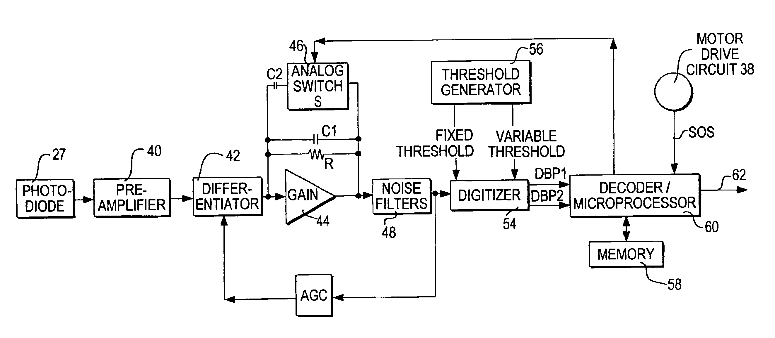
Thus, this invention filters an analog signal with a first bandpass characteristic and obtains two digitized signals, each with a different threshold, during a first scan. Thereupon, during a second subsequent scan, the analog signal is filtered with a second different bandpass characteristic and obtains two more digitized signals, again each with a different threshold. This process continues, if necessary, until the symbol is successfully read. There are no separate preamplifiers, or filters, or threshold generators, or analog-to-signal generators. Multiple, different outputs during successive scans increase the chances that the symbol will be read, thereby improving reader performance.

Problems solved by technology

The data collection circuit will, however, not be able to readily read, if at all, the symbol if the symbol is poorly printed or damaged.
However, if the threshold is set too high, a high level of noise resulting from printed imperfections may be thresholded out, but at the risk of thresholding out a weak signal for an actual element of the symbol.
If the threshold is set too low, noise may be detected as data elements of the bar code.
Hence, a single threshold is not well suited to enable a reader to readily read symbols of different print qualities, at different distances from the reader, of different symbol densities, and under different real world conditions.
However, it often takes several scans before a workable threshold is selected for a particular symbol being scanned.
As a result, although the reader will ultimately be able to read the symbol, the reader will feel sluggish.
The characteristics of the filter and the threshold generator, for example, do not change from one scan to the next, and their default values may not be adequate to allow the symbol to be read.
In addition, there is much extra cost and complexity involved in providing two identical collection channels with the same components.

Method used


Image

  • Data collection signal processing for increased performance in electro-optical readers
  • Data collection signal processing for increased performance in electro-optical readers
  • Data collection signal processing for increased performance in electro-optical readers

Examples


Embodiment Construction

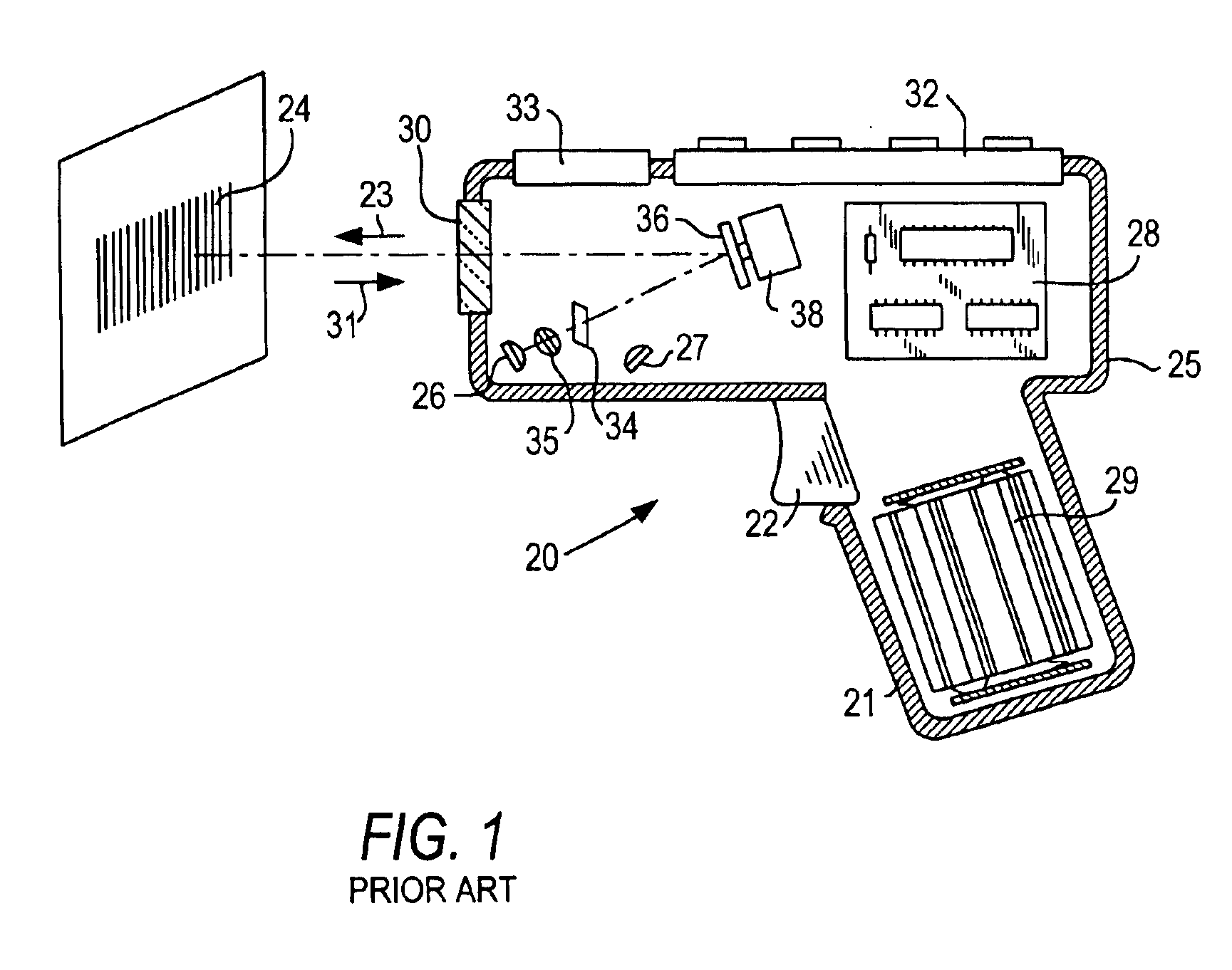
Reference numeral 20 in FIG. 1 generally identifies a hand-held reader for electro-optically reading indicia, such as bar code symbol 24, located in a range of working distances therefrom. The reader 20 has a pistol grip handle 21 and a manually actuatable trigger 22 which, when depressed, enables a light beam 23 to be directed at the symbol 24. The reader 20 includes a housing 25 in which a light source 26, a light detector 27, signal processing circuitry 28, and a battery pack 29 are accommodated. A light-transmissive window 30 at a front of the housing enables the light beam 23 to exit the housing, and allows light 31 scattered off the symbol to enter the housing. A keyboard 32 and a display 33 may advantageously be provided on a top wall of the housing for ready access thereto.

In use, an operator holding the handle 21 aims the housing at the symbol and depresses the trigger. The light source 26 emits a light beam which is optically modified and focused by an optical focusing ass...


PUM


Abstract

Signal processing performance in electro-optical readers is improved by changing filter characteristics and / or digitizer thresholds during successive scans.

Description

BACKGROUND OF THE INVENTION1. Field of the InventionThe present invention generally relates to electro-optical systems for reading indicia, for example, bar code symbols, having parts with different light reflectivities and, in particular, to an arrangement for, and a method of, improving the performance of data collection.2. Description of the Related ArtVarious electro-optical readers and systems have previously been developed for reading bar code symbols appearing on a label, or on a surface of a target. The bar code symbol itself is a coded pattern of indicia. Generally, the readers electro-optically transform graphic indicia of the symbols into electrical signals which are decoded into alphanumeric characters. The resulting characters describe the target and / or some characteristic of the target with which the symbol is associated. Such characters typically comprise input data to a data processing system for applications in point-of-sale processing, inventory control, article tr...

Claims


Application Information

Patent Timeline
Patent Type & Authority Patents(United States)
IPC IPC(8): G06K7/10
CPCG06K7/10851
Inventor BARKAN, EDWARD
Owner SYMBOL TECH LLC
Learn More