
Method and apparatus for coupling a sample probe with a sample site

a sample probe and sample site technology, applied in the field of nearinfrared spectroscopy non-invasive measurement of biological parameters, can solve the problems of unsuitable chlorofluorocarbons (cfc's) for preparations to be used on living tissue, abnormal production and use of insulin,

Active Publication Date: 2014-05-06
GLT ACQUISITION
View PDF169 Cites 459 Cited by
  • Summary
  • Abstract
  • Description
  • Claims
  • Application Information

AI Technical Summary

Problems solved by technology

Diabetes is a chronic disease that results in abnormal production and use of insulin, a hormone that facilitates glucose uptake into cells.
However, current monitoring techniques discourage regular use due to the inconvenient and painful nature of drawing blood through the skin prior to analysis.
Since they are known carcinogens, chlorofluorocarbons (CFC's) are unsuitable for use in preparations to be used on living tissue.
Furthermore, use of CFC's poses a well-known environmental risk.

Method used


Image

  • Method and apparatus for coupling a sample probe with a sample site
  • Method and apparatus for coupling a sample probe with a sample site
  • Method and apparatus for coupling a sample probe with a sample site

Examples


Embodiment Construction

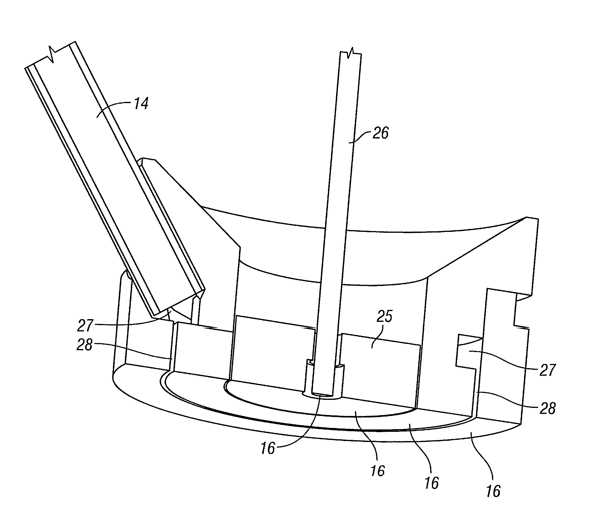
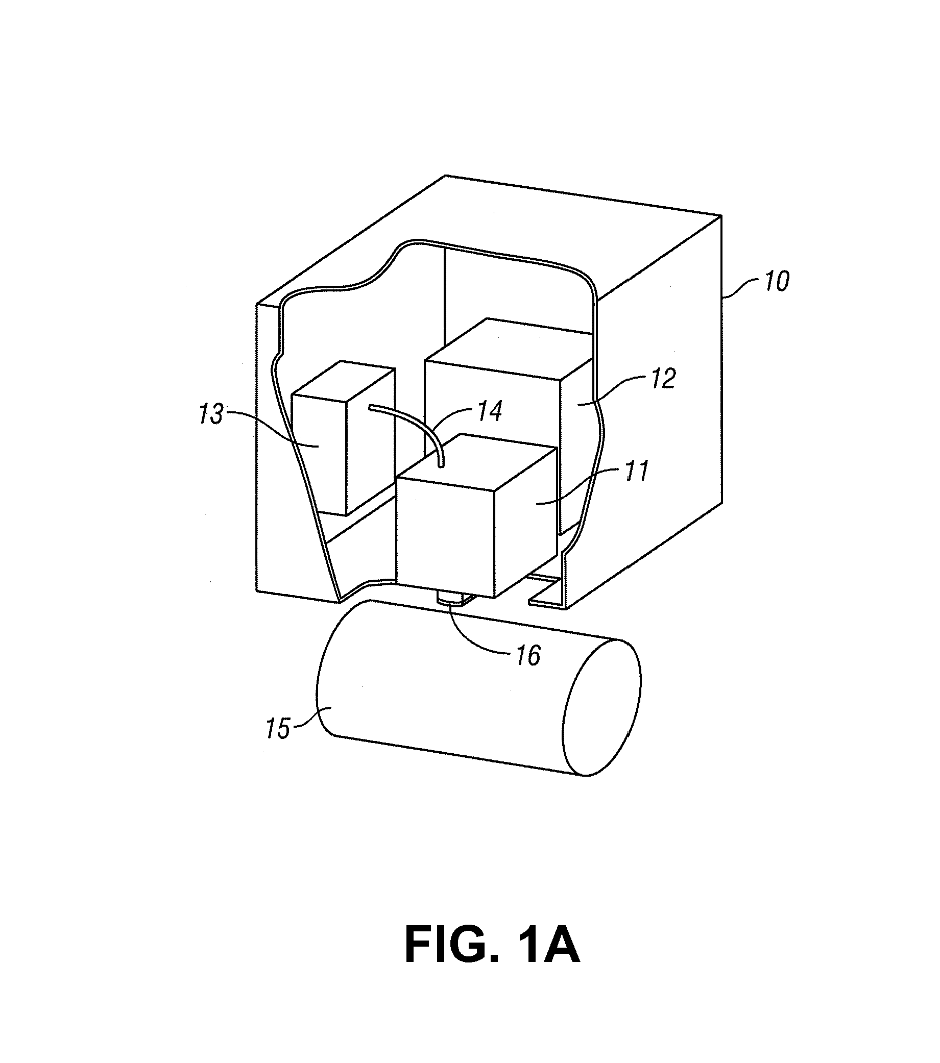
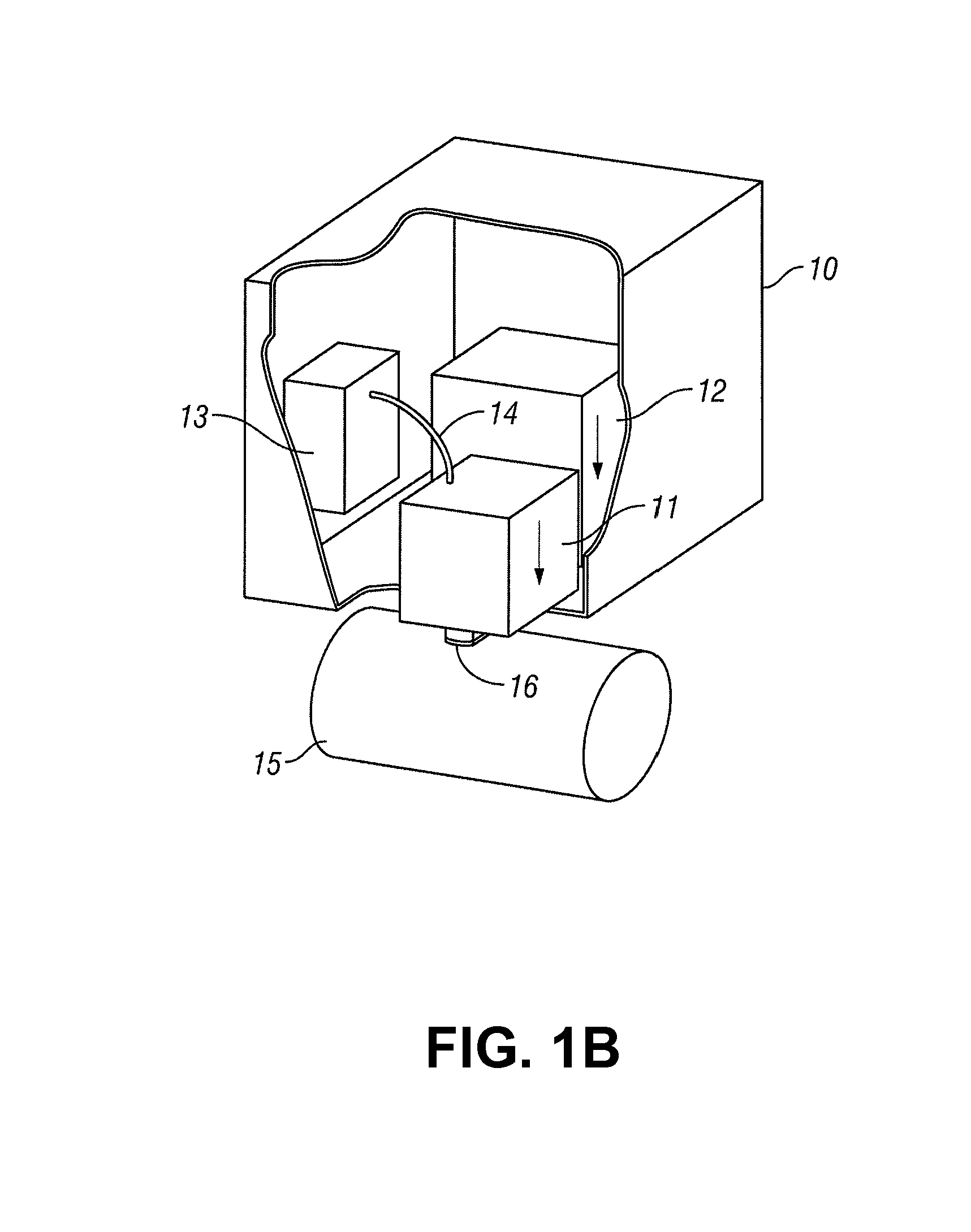
[0043]The invention comprises a fluid delivery method and apparatus between a sample probe and a sample.

[0044]In one embodiment, a fluid delivery system includes use of: a fluid reservoir, a delivery channel, a manifold or plenum, a channel or moat, a groove, and / or a dendritic pathway to deliver a fluid to a sample probe head and / or a sample. For example, the fluid delivery system is used to place the fluid in a uniform manner substantially or completely covering a sample site, thus minimizing sampling errors due to mechanical tissue distortion, specular reflectance, probe placement, and / or mechanically induced sample site stress / strain is concurrent or subsequent optical sampling of the sample.

[0045]For example, a fluid or coupling fluid is delivered to a sample using the fluid delivery system. The fluid placed on the surface of tissue at a tissue measurement site, such as a coupling medium or alternatively an optical coupling fluid, is used to enhance performance of an optical an...


PUM


Abstract

The invention comprises method and apparatus for fluid delivery between a sample probe and a sample. The fluid delivery system includes: a fluid reservoir, a delivery channel, a manifold or plenum, a channel or moat, a groove, and / or a dendritic pathway to deliver a thin and distributed layer of a fluid to a sample probe head and / or to a sample site. The fluid delivery system reduces sampling errors due to mechanical tissue distortion, specular reflectance, probe placement, and / or mechanically induced sample site stress / strain associated with optical sampling of the sample.

Description

CROSS REFERENCE TO RELATED APPLICATION[0001]This application:[0002]is a continuation-in-part of U.S. patent application Ser. No. 11 / 031,103, filed Jan. 6, 2005, which claims priority from U.S. provisional patent application Ser. No. 60 / 536,197, filed Jan. 12, 2004; U.S. provisional patent application Ser. No. 60 / 534,834, filed Jan. 6, 2004; and U.S. provisional patent application Ser. No. 60 / 566,568, filed Apr. 28, 2004;[0003]is a continuation-in-part of U.S. patent application Ser. No. 11 / 335,773, filed Jan. 18, 2006, which is a continuation of U.S. patent application Ser. No. 10 / 472,856, filed Sep. 18, 2003, which claims priority from PCT application no. PCT / US03 / 07065, filed Mar. 7, 2003, which claims benefit of U.S. provisional patent application Ser. No. 60 / 362,885, filed Mar. 8, 2002; and[0004]claims benefit of U.S. provisional patent application No. 61 / 032,859, filed Feb. 29, 2008,[0005]all of which are incorporated herein in their entirety by this reference thereto.BACKGROUN...

Claims


Application Information

Patent Timeline
Patent Type & Authority Patents(United States)
IPC IPC(8): A61B5/00G02B6/24
CPCA61B5/14532A61B2562/146G01N21/01G01N21/359G01N21/474A61B5/1455A61B5/0075
Inventor BLANK, THOMAS B.ABUL-HAJ, ROXANNE E.
Owner GLT ACQUISITION
Learn More