
Antenna array system

a technology of antenna array and base station, which is applied in the direction of duplex signal operation, code conversion, instruments, etc., can solve the problems of inconvenient installation, inconvenient installation, and inconvenient installation,

Active Publication Date: 2014-04-29
TELEFON AB LM ERICSSON (PUBL)
View PDF48 Cites 9 Cited by
  • Summary
  • Abstract
  • Description
  • Claims
  • Application Information

AI Technical Summary

Benefits of technology

This solution minimizes signal loss, reduces space and power needs, simplifies installation, and enhances aesthetic appeal by eliminating unsightly coaxial cables while maintaining efficient communication capabilities.

Problems solved by technology

This, however, is not always wanted and frequently raises concerns with residents living close to the antennas.
At present the base station requires a considerable amount of space, usually of the size of a small room.
The cable length has the inherent disadvantages of energy and signal to noise loss.
The coaxial cable often runs along the outside of the building and is as a result unsightly.

Method used


Image

  • Antenna array system
  • Antenna array system
  • Antenna array system

Examples


Embodiment Construction

[0057]It should be appreciated that the various aspects of what is taught herein are merely illustrative of the specific ways to make and use the taught antenna array system and do not limit the scope of what is claimed herein when taken into consideration with the claims and the following detailed description and the accompanying Figures. It should be observed that features from one aspect of what is taught herein can be combined with features from other aspects of the teachings disclosed herein.

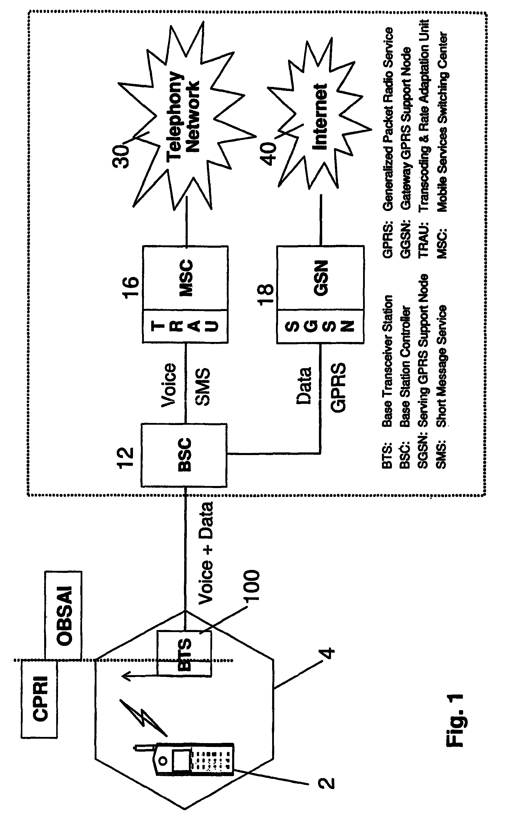
[0058]FIG. 1 shows an overview of a mobile communications network. A mobile station 2 can communicate via radio links with a base transceiver station (BTS) 100 when the mobile station 2 is within the range 4 of the BTS 100. A mobile station 2 is any mobile or immobile communication device that enables communication via radio links, usually at radio frequencies (RF) in the range of 800 MHz up to several GHz. Common examples for mobile stations are, but are not limited to, mobile telephones, ...


PUM


Abstract

Antenna system connectable to a base station, the antenna system comprising a digital radio unit connectable to at least one antenna element, wherein the digital radio unit comprises: at least one micro radio for receiving / sending digital radio signals having a digital down-converter / a digital up-converter and a digital signal converter. The at least one micro radio converts the digital radio signals to analogue RF (radio frequency) signals and vice versa. The at least one micro radio has at least one hub for processing digital radio signals and control signals and for routing said digital radio signals and control signals via at least one serial link and at least one interface. The at least one serial link is provided between the at least one hub and the at least one micro radio.

Description

RELATED APPLICATIONS[0001]This application is a continuation-in-part of International Patent Application No. PCT / EP2007 / 006334, filed 17 Jul. 2007, which claims priority of U.S. provisional application 60 / 807,509, filed 17 Jul. 2006, and of UK patent application GB 0614299.6, filed 17 Jul. 2006. The entire disclosure of each of the foregoing application is incorporated herein by reference.FIELD OF THE INVENTION[0002]The present application relates to radio transceivers and antenna systems. In particular, the present invention relates to base transceiver stations and antennas for mobile communication systems.BACKGROUND[0003]Mobile communication technology has greatly advanced in recent years, as evident by the high performance digital mobile phones currently available. Mobile communication has been made available with almost 100% coverage area in many regions of the world following the demand of the users. Users wish to be able to communicate via their mobile phone (mobile stations) ...

Claims


Application Information

Patent Timeline
Patent Type & Authority Patents(United States)
IPC IPC(8): H04B1/38H04W16/24H04W88/08
CPCH04B1/40H04W16/24H04W88/08H04B1/18H04W88/085
Inventor RHEINFELDER, CLEMENSKORTE, WERNER
Owner TELEFON AB LM ERICSSON (PUBL)
Learn More