Repeller structure and ion source

a technology of ion source and ion beam, which is applied in the field of ion source, can solve the problems of large repeller, difficult to increase the surface area of the sputtering target, and large size of the repeller, so as to simplify the structure of mounting the sputtering target, increase the dimension of the sputtering surface as large, and enhance the reflection efficiency of electrons emitted

Active Publication Date: 2014-04-22
NISSIN ION EQUIP CO LTD
View PDF10 Cites 10 Cited by
  • Summary
  • Abstract
  • Description
  • Claims
  • Application Information

AI Technical Summary

Benefits of technology

[0009]The present invention has been achieved to solve at least the above problems. An object of the present invention is to make the dimension of the sputtering surface as large as possible. Another object is to simplify a mounting structure of the sputtering target. Still another object is to enhance the reflection efficiency of the electrons emitted from the cathode while maintaining compact size of the repeller structure.
[0011]With the above configuration, because the through hole is provided on the sputtering target and the electrode body is inserted in the through hole, a surface area of the sputtering surface of the sputtering target can be increased as large as possible regardless of the configuration of the repeller in the plasma generating chamber, which makes it possible to generate ions in a stable manner for a long time. Furthermore, because it is possible not only to downsize the electrode body but also to fix the sputtering target to the electrode body with a simple structure, a replacement operation of the sputtering target can be easily performed. In addition, because the repeller surface is exposed through the through hole of the sputtering target, the repeller surface can be arranged facing the portion to which the electrons are emitted, and the reflection efficiency of the electrons emitted from the cathode can be enhanced. As a result, the plasma generation efficiency can be enhanced.
[0012]It is preferable that the sputtering target includes a counterboring portion formed with a diameter larger than that of an opening of the through hole on the sputtering surface, the electrode body includes a large diameter portion on its end portion, which is engaged with the counterboring portion, and an end surface of the large diameter portion serves as a repeller surface. With this configuration, it is possible to perform a positioning of the sputtering target and the electrode body in a simple manner. Furthermore, if the repeller structure is arranged vertically downwards, it is possible to eliminate other fixing parts, which makes it possible to form the repeller structure in an extremely simple structure.
[0018]According to the embodiments of the present invention, it is possible to increase the dimension of the sputtering surface as large as possible, enhance the reflection efficiency of the electrons emitted from the cathode, simplify the structure of mounting the sputtering target, and make the repeller structure compact.

Problems solved by technology

However, because the outer peripheral surface of the sputtering target is fixed by the repeller in a limited space in a plasma generating chamber, there is restriction in the size of the repeller.
That also causes the size of the sputtering target to be contained in the repeller to be restricted, which leads to a problem that it is difficult to increase the surface area of the sputtering target.
There is another problem that a larger repeller must be used because the repeller is arranged on the outer peripheral surface of the sputtering target.
Furthermore, because the thread portion is provided on the tubular inner surface of the repeller, not only the structure of the repeller becomes complicated, but also material cost and processing cost could increase if the repeller is manufactured by machining a single workpiece.
In addition, because the repeller is arranged on the outer circumference of the sputtering target with respect to electrons emitted from the cathode, a member facing a portion from where the electrons are emitted from the cathode becomes the sputtering target, resulting in a problem that the electron reflection efficiency is degraded, and as a result, the plasma generation efficiency is degraded.

Method used


Image

  • Repeller structure and ion source
  • Repeller structure and ion source
  • Repeller structure and ion source

Examples


Embodiment Construction

[0026]Exemplary embodiments of an ion source according to the present invention will be explained in detail below with reference to the accompanying drawings.

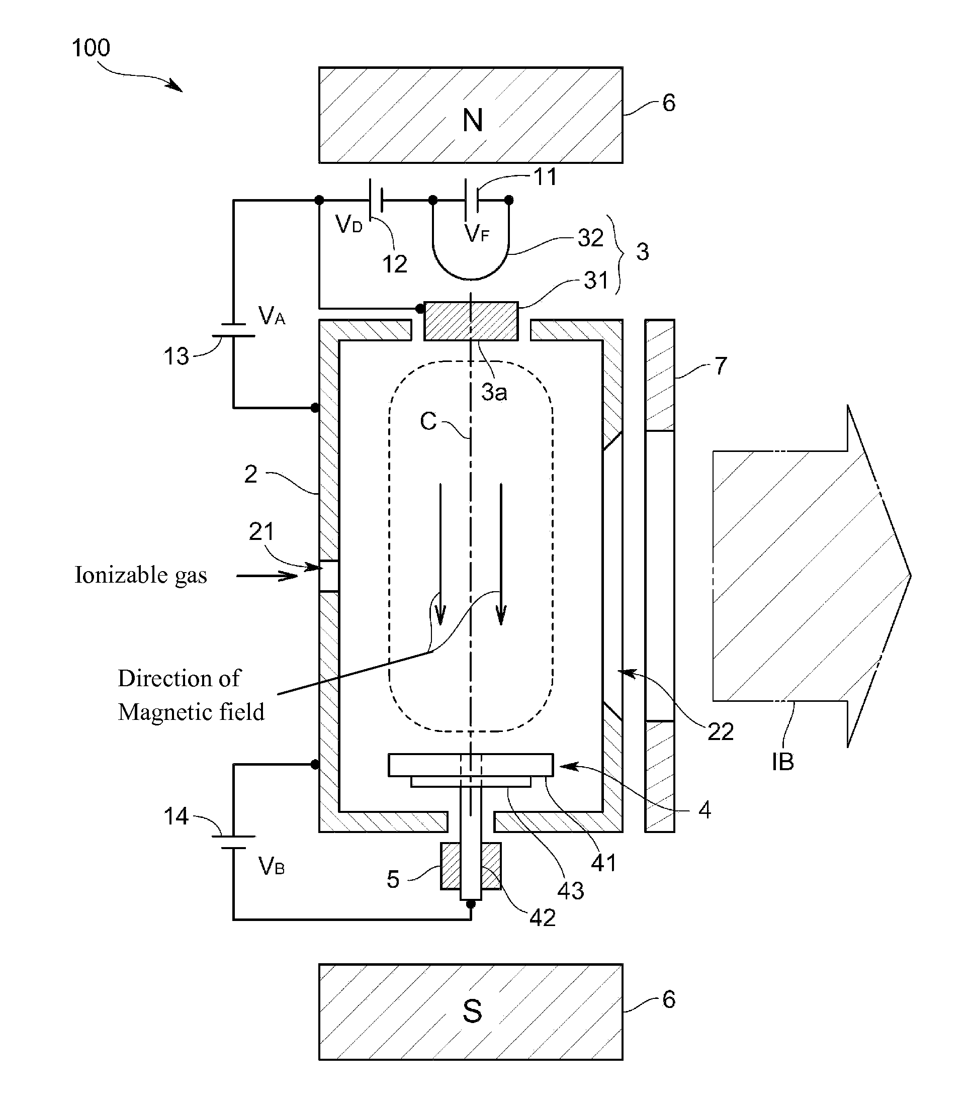
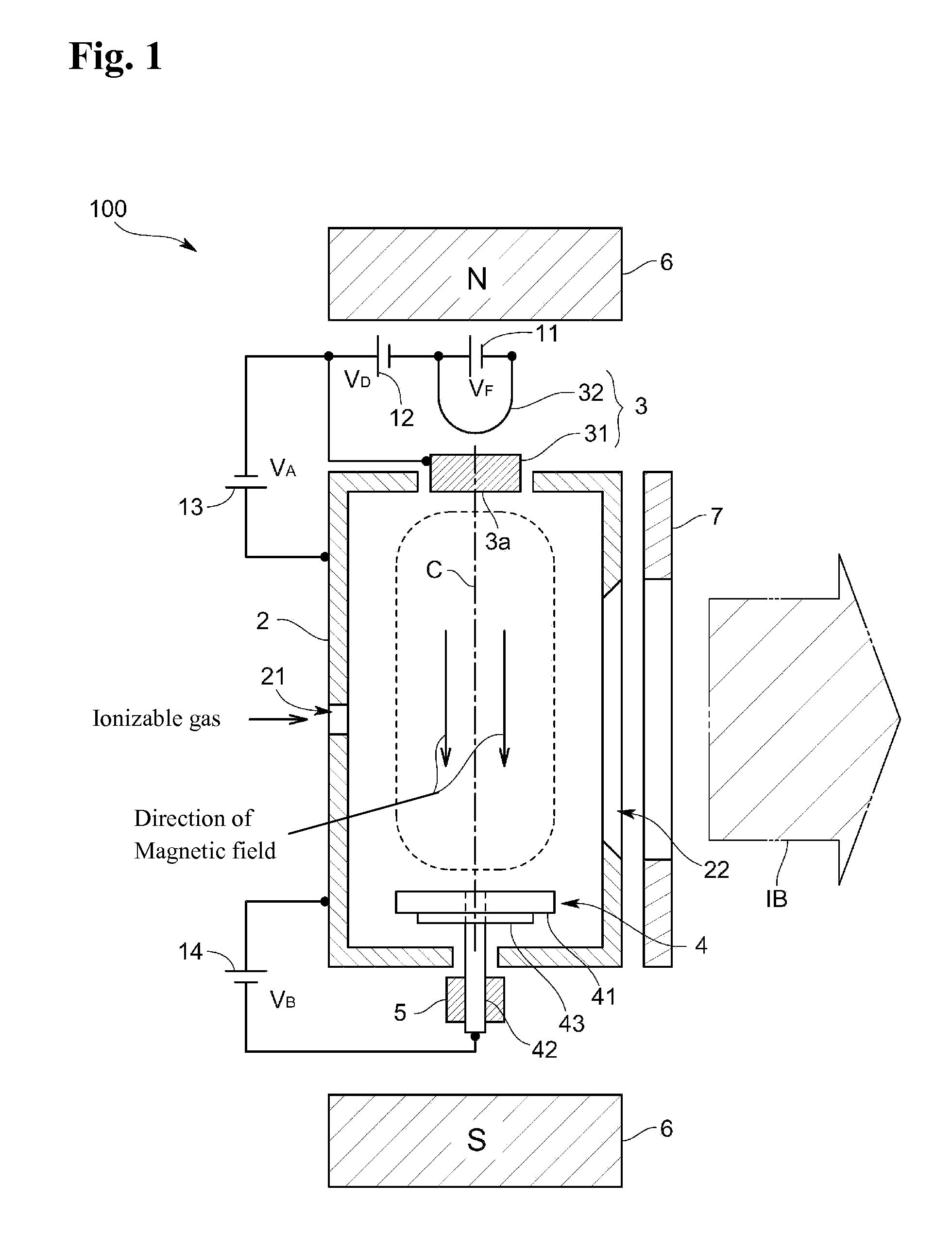
[0027]An ion source 100 according to an embodiment of the present invention is shown in FIG. 1. The ion source 100 generates an ion beam IB that contains predetermined ions such as aluminum ions. The ion source 100 includes a plasma generating chamber 2, an indirectly heated cathode 3 provided on the plasma generating chamber 2, and a repeller structure 4 arranged in the plasma generating chamber 2, facing the indirectly heated cathode 3.

[0028]The plasma generating chamber 2, the indirectly heated cathode 3, and the repeller structure 4 are explained in detail below.

[0029]The plasma generating chamber 2 has, for example, a rectangular cuboid shape in which a plasma is generated. The plasma generating chamber 2 also serves as an anode for arc discharge. The plasma generating chamber 2 has a gas inlet port 21 for introducing an i...


PUM

PropertyMeasurementUnit
bias voltageaaaaaaaaaa
electrically conductiveaaaaaaaaaa

Abstract

A repeller structure is provided in a plasma generating chamber of an ion source facing a cathode that emits electrons for ionizing a source gas in the plasma generating chamber to generate a plasma. The repeller structure reflects the ions toward the cathode. The repeller structure includes a sputtering target that is sputtered by the plasma to emit predetermined ions, the sputtering target including a through hole that connects a sputtering surface and a back surface of the sputtering target; and an electrode body that is inserted in the through hole, the electrode body including a repeller surface that is exposed to the sputtering surface side through the through hole.

Description

BACKGROUND OF THE INVENTION[0001]1. Field of the Invention[0002]The present invention relates to an ion source. More particularly, the present invention relates to a repeller structure configured to be mounted in a plasma generating chamber of an ion source. Such a repeller structure is typically arranged opposite to a cathode that emits electrons to repel the electrons toward the cathode.[0003]2. Description of the Related Art[0004]In recent years, a technique is considered in which, a source gas is ionized in a plasma generating chamber of an ion source by a cathode to generate a plasma and a sputtering target is sputtered by the plasma to cause desired ion species to be contained in an ion beam.[0005]Specifically, as described in Japanese Patent Application Laid-open No. 2002-117780, a sputtering target provided at an end portion of a repeller is held in a replaceable manner to make it possible to generate stable ion species. The detailed structure includes a tubular repeller and...

Claims


Application Information

Patent Timeline
Patent Type & Authority Patents(United States)
IPC IPC(8): C23C14/00
CPCH01J27/022
Inventor IKEJIRI, TADASHIIGO, TETSUYAYAMASHITA, TAKATOSHI
Owner NISSIN ION EQUIP CO LTD
Why Eureka
Try Eureka