
Process for producing a turbulence apparatus

Inactive Publication Date: 2014-04-22
BEHR GMBH & CO KG
View PDF15 Cites 0 Cited by
  • Summary
  • Abstract
  • Description
  • Claims
  • Application Information

AI Technical Summary

Benefits of technology

The present invention provides a process for producing a turbulence device for insertion into a heat exchanger without cutting burrs at the cutting sites. The process includes a cutting step prior to a rolling step, which allows for precise length control of the turbulence device. The rolling step includes intermediate steps to gradually shape the turbulence device and ensure uniform material thickness. The finished device has a thin sheet metal thickness from 0.05 mm to 0.35 mm. A transfer station is also provided for rapid and cost-effective fitting of the turbulence device into heat exchanger tubes.

Problems solved by technology

In this case, however, the production times are long and the production costs correspondingly high.
This similarly gives rise to long production times and high production costs, particularly due to the assembly process.
The processes have different cycle times, however, so that the more time-consuming stamping process, in particular, takes longer than the longitudinal rolling process for producing the preliminary stage of the turbulence device with merely smooth walls.
Owing to the thin basic material, the process of cutting the turbulence devices to any predetermined, freely selectable length is particularly difficult, since the areas in which a cut is made through the turbulence device has to be precisely fixed, in order to obtain a precise cut substantially without any cutting burrs, since the cutting burrs reduce the heat transfer efficiency and increase the pressure loss.
The complex structure of the turbulence device with undercuts and offsets makes this cutting operation problematical.

Method used


Image

  • Process for producing a turbulence apparatus
  • Process for producing a turbulence apparatus
  • Process for producing a turbulence apparatus

Examples


Embodiment Construction

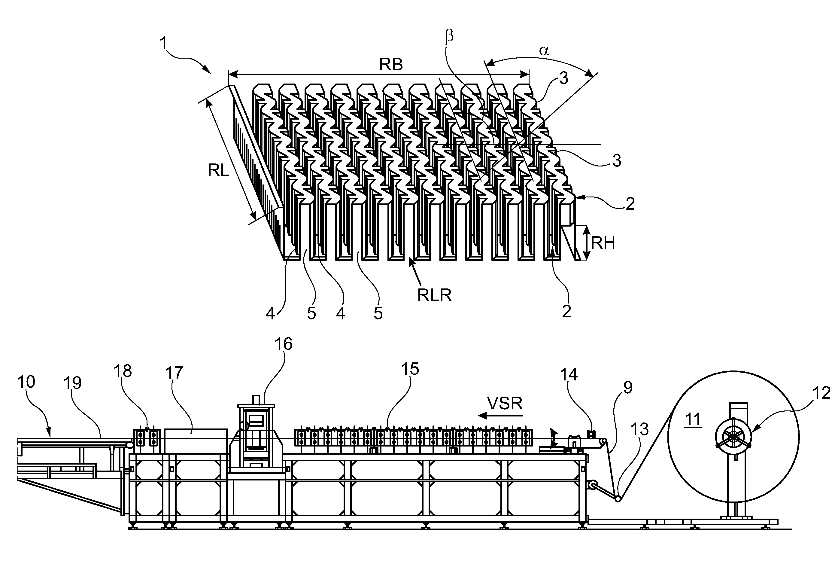
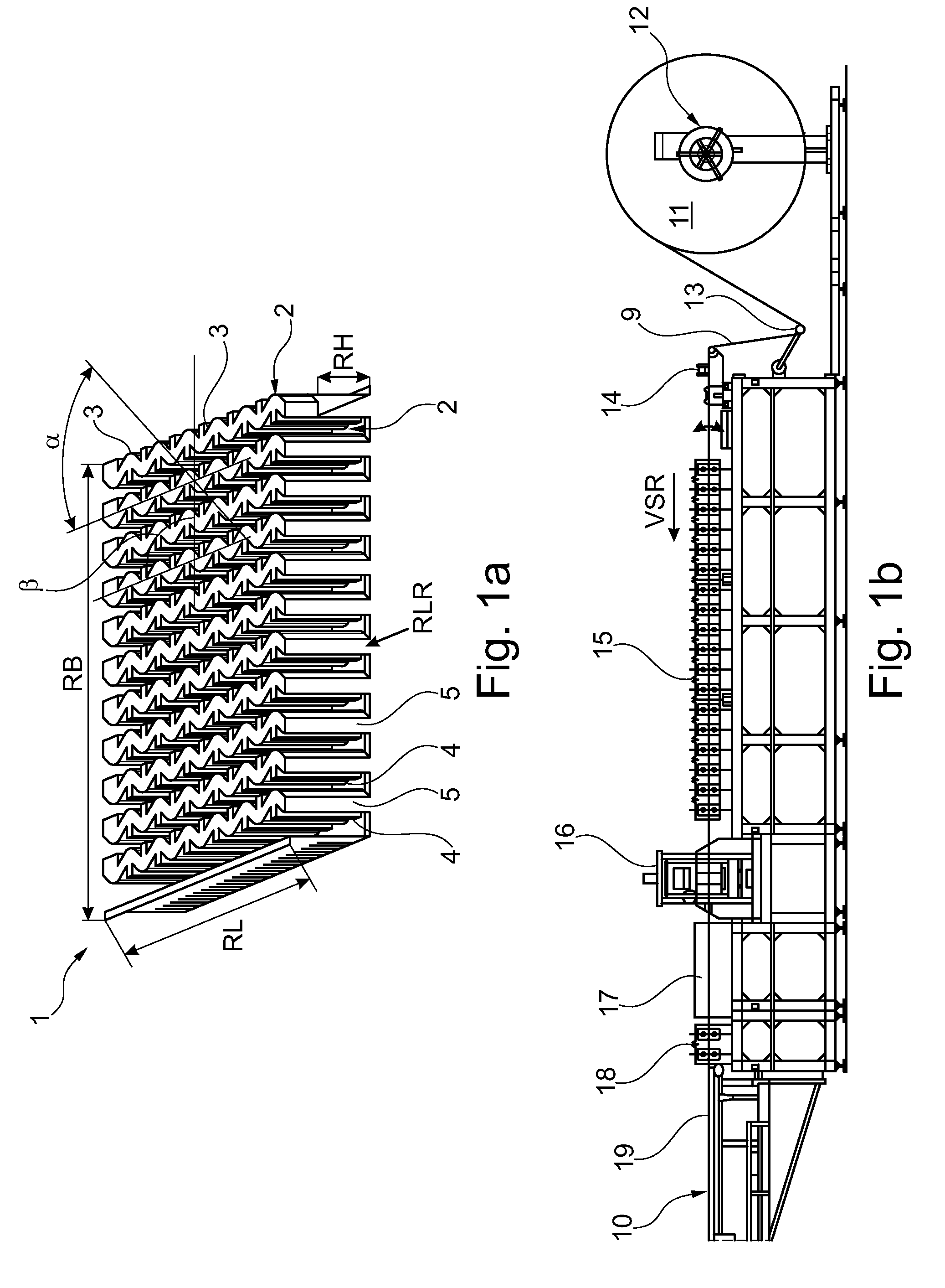
[0040]FIG. 1a shows a turbulence fin 1. The turbulence fin 1 has a fin width RB and a fin length RL. The turbulence fin 1 is of substantially meandering design and has a number of troughs 4, and correspondingly formed, associated peaks 5, a trough 4 in each case alternating with a peak 5.

[0041]The peak 5 is substantially a fin trough 4 turned through 180°. The fin troughs 4 and the fin peaks 5 have fin impressions 3, which are impressed into the fin peaks 5 and the fin troughs 4. Fin impressions substantially have a pyramidal shape, in particular the shape of a 4-sided pyramid or in another embodiment they may have a cuboidal shape. The fin peaks 5 and the fin troughs are defined by fin walls 2. Reference is made, with regard to the turbulence fin 1, to the unpublished DE 10 2007 014 138.8 by the present applicant, which is hereby expressly incorporated into the disclosure of this application. The turbulence fin 1 is formed from a metallic material, such as aluminum or steel, for ex...


PUM

PropertyMeasurementUnit
Thicknessaaaaaaaaaa
Thicknessaaaaaaaaaa
Thicknessaaaaaaaaaa

Abstract

A process for producing a turbulence device (1) which is to be mounted in at least one flow duct of a heat exchanger of a motor vehicle includes the steps of, in a first process step, at least one shaping operation is used to produce at least one substantially meandering turbulence device (30) with substantially smooth walls (2) from a substantially continuously planar sheared strip (9), wherein a longitudinal direction (RLR) of the walls runs substantially parallel to a forward feed direction (VSR) of the sheared strip (9), and in a second process step, wall sections are deformed at least by an angle (α) in relation to the forward feed direction (VSR), in such a way that undercuts (3) are produced in relation to the forward feed direction (VSR, RLR), wherein the substantially continuously planar sheared strip (9) is cut into turbulence devices (1) of predetermined lengths before carrying out the second process step.

Description

BACKGROUND OF THE INVENTION[0001]The present invention relates to a process for producing a turbulence device which is to be mounted in at least one flow duct of a heat exchanger of a motor vehicle, comprising the following process steps: in a first process step, at least one shaping operation is used to produce at least one substantially meandering turbulence device with substantially smooth walls from a substantially continuously planar sheared strip, wherein a longitudinal direction of the walls runs substantially parallel to a forward feed direction of the sheared strip. In a second process step, wall sections are deformed at least by an angle α in relation to the forward feed direction, in such a way that undercuts are produced in relation to the forward feed direction.[0002]The invention further relates to an apparatus for carrying out a process as described herein, comprising at least one set of rollers for successively shaping the sheared strip, in particular the sheet-metal...

Claims


Application Information

Patent Timeline
IPC IPC(8): B21D53/02
CPCB21D13/045B21D53/04F28F3/027Y10T29/53122Y10T428/12417Y10T29/4935
Inventor PAULIK, JENSHAGELE, JURGENOSWALD, WERNERUTZ, ACHIM
Owner BEHR GMBH & CO KG
Learn More