
Method for shaping wing velocity profiles for control of flapping wing micro air vehicles

a technology of micro air vehicles and wing velocity profiles, which is applied in the direction of navigation instruments, instruments, ornithopters, etc., can solve the problems that none of these efforts have resulted in aircraft capable of six-degrees of freedom flight, and achieve the effect of reducing the weight and complexity of the aircraft and enhancing its performan

Active Publication Date: 2014-04-15
UNITED STATES OF AMERICAS AS REPRESENTED BY THE SEC OF THE AIR FORCE THE
View PDF26 Cites 41 Cited by
  • Summary
  • Abstract
  • Description
  • Claims
  • Application Information

AI Technical Summary

Benefits of technology

This patent describes a method and device that allows small drones to move like insects with just two physical actuators and limited computer processing power. The method and device enable controlled flight with six degrees of freedom using position and velocity profiles that can be adjusted to generate controllable forces and moments. This approach reduces the weight and complexity of the drone while improving its performance.

Problems solved by technology

However, none of these efforts has resulted in an aircraft capable of six-degrees-of-freedom flight with only two actuators.

Method used


Image

  • Method for shaping wing velocity profiles for control of flapping wing micro air vehicles
  • Method for shaping wing velocity profiles for control of flapping wing micro air vehicles
  • Method for shaping wing velocity profiles for control of flapping wing micro air vehicles

Examples


Embodiment Construction

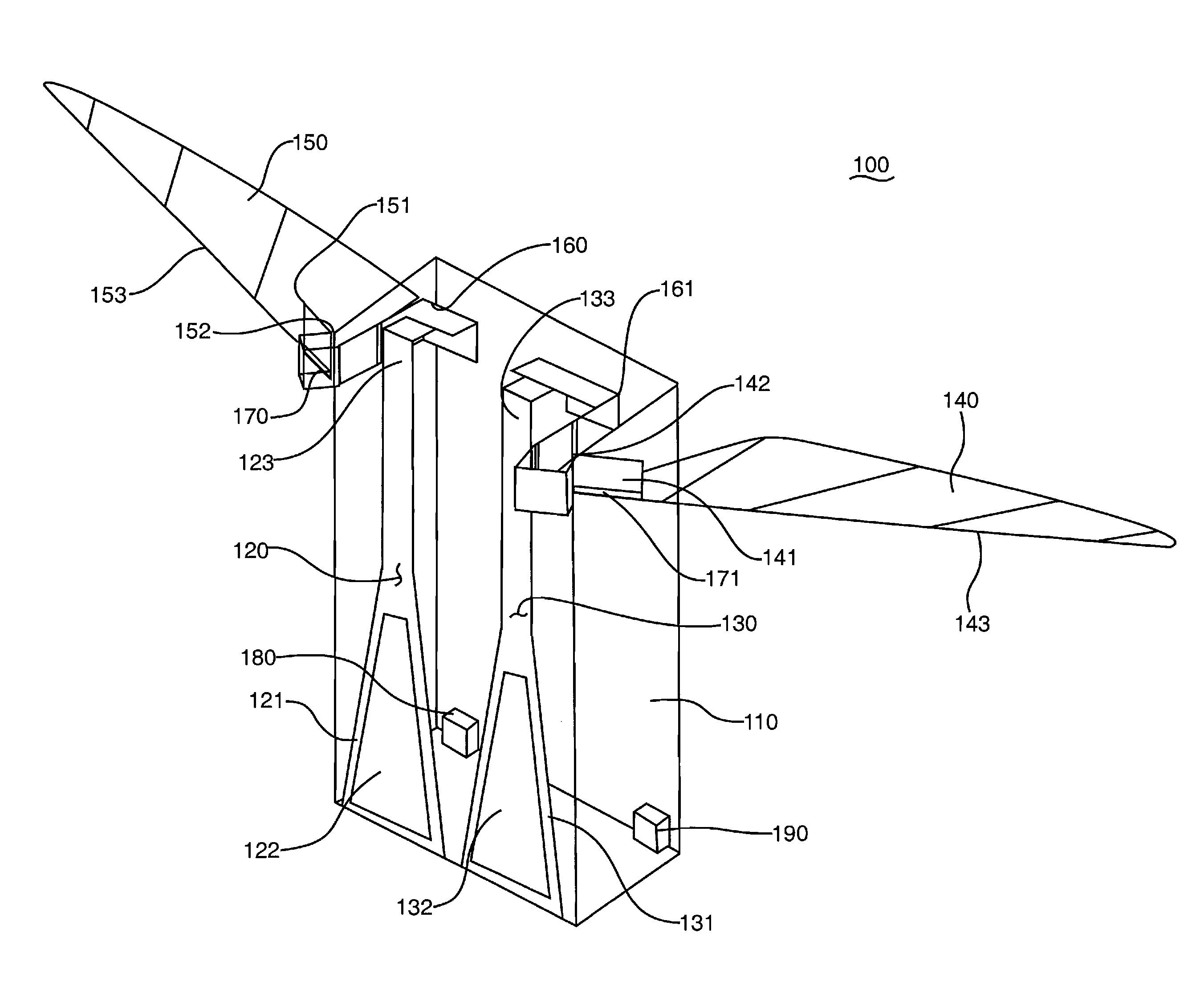
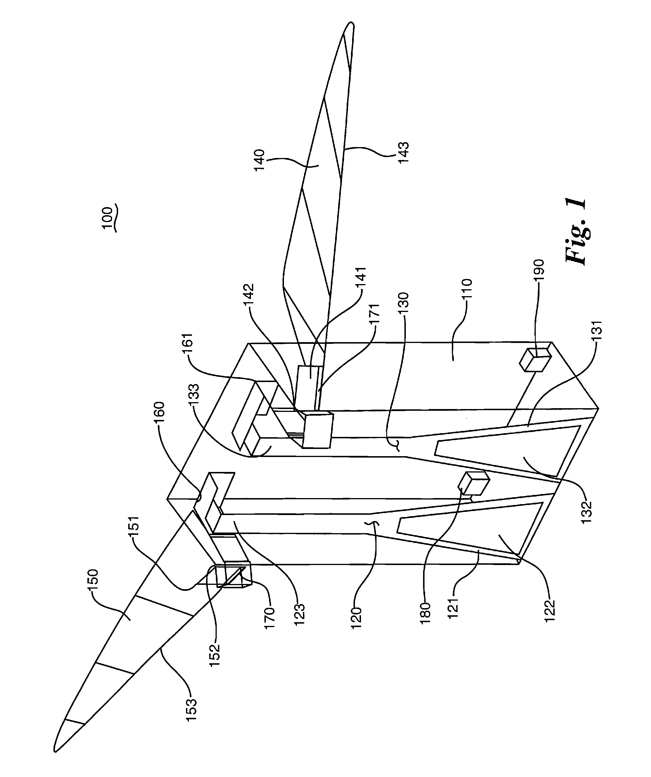
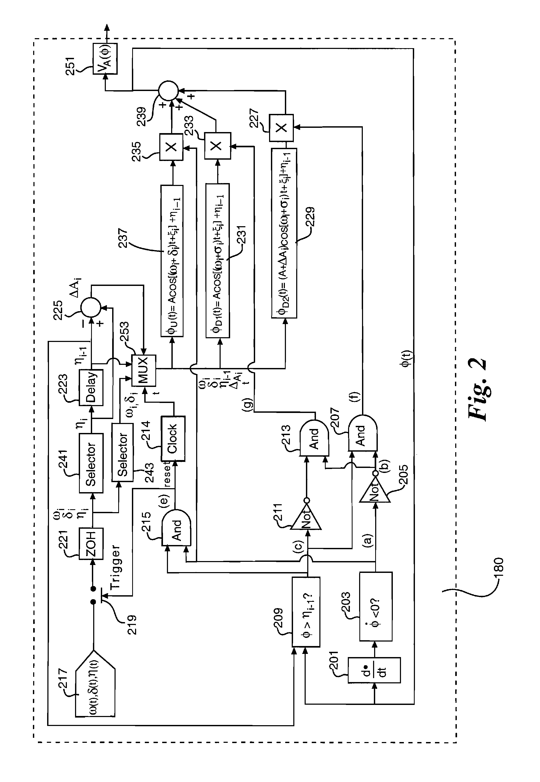
[0015]As shown in FIG. 1, an aircraft 100 comprises a fuselage 110, biomorph actuators 120, 130, wing planforms 140, 150, linkages 160, 161, flexure joints 170, 171, wing roots 141, 151, wing root hinges 142, 152, a flight control wave form generator 180, and a power source 190.

[0016]Each wing planform 140, 150 is rigidly attached to a wing spar 143, 153 that extends along a leading edge of a respective wing planform 140, 150. Each wing spar 143, 153 is connected to a linkage 160, 161 via a flexure joint 170, 171. Each wing spar 143, 153 is also connected to a wing root 141, 151. Each wing root 141, 151 connects to the fuselage 110 via one of the wing root hinges 142, 152. The connection of the wing spars 143, 153 to the flexure joints 170, 171 allows the wing planforms 140, 150 to move passively about a longitudinal axis of each respective wing spar 143, 153 between ±45° with respect to the stroke plane of each wing planform 140, 150. The stroke plane of each wing spar 143, 153 is ...


PUM


Abstract

A method of controlling wing position and velocity for a flapping wing air vehicle provides six-degrees-of-freedom movement for the aircraft through a split-cycle constant-period frequency modulation with wing bias method that generates time-varying upstroke and downstroke wing position commands for wing planforms to produce nonharmonic wing flapping trajectories that generate non-zero, cycle averaged wing drag and alter the location of the cycle-averaged center of pressure of the wings relative to the center of gravity of the aircraft to cause horizontal translation forces, rolling moments and pitching moments of the aircraft.

Description

CROSS REFERENCE TO RELATED APPLICATIONS[0001]This application claims benefit of priority from U.S. Provisional Application Ser. No. 61 / 368,670, which was filed in the United States Patent and Trademark Office on Jul. 29, 2010.RIGHTS OF THE GOVERNMENT[0002]The invention described herein may be manufactured and used by or for the Government of the United States for all governmental purposes without the payment of any royalty.TECHNICAL FIELD[0003]This application discloses methods and apparatuses that shape wing velocity profiles for controlling flapping wing micro air vehicles.BACKGROUND[0004]Research in the area of flapping wing flight has been conducted by the biological and engineering communities. Researchers have studied the flight dynamics of animals and ornithopters. However, none of these efforts has resulted in an aircraft capable of six-degrees-of-freedom flight with only two actuators.SUMMARY OF INVENTION[0005]The disclosed method and apparatus enable biomimetic micro-robot...

Claims


Application Information

Patent Timeline
Patent Type & Authority Patents(United States)
IPC IPC(8): B64C33/00
CPCB64C2201/042B64C2201/025B64C39/028B64C33/02B64C33/00B64U10/40B64U10/80B64U30/12
Inventor DOMAN, DAVID B.OPPENHEIMER, MICHAEL W.
Owner UNITED STATES OF AMERICAS AS REPRESENTED BY THE SEC OF THE AIR FORCE THE
Learn More