Lubrication system for four-stroke engine

a lubrication system and four-stroke technology, applied in the direction of auxilary lubrication, lubrication elements, lubrication of crankcase compression engines, etc., can solve the problems of affecting the lubrication of driving components, reducing so as to reduce the concentration of oil mist, the effect of further suppressing the oil consumption

Active Publication Date: 2014-04-15
MARUYAMA MFG CO INC
View PDF24 Cites 5 Cited by
  • Summary
  • Abstract
  • Description
  • Claims
  • Application Information

AI Technical Summary

Benefits of technology

[0014]The present invention has been made in view of the above circumstances, and it is an object of the invention to provide a lubrication system for a four-stroke engine that can lubricate a crank chamber and other driving systems with oil at suitable concentrations to prevent an increase in oil consumption.
[0015]It is another object of the invention to provide a lubrication system for a four-stroke engine which can prevent lubrication failure from occurring around a crankshaft and can also reliably prevent the accumulation of oil in the valve-operating chamber from occurring.

Problems solved by technology

In this state, if the blow-by gas remains mixed with the oil, the oil is gradually degraded, and this adversely affects the lubrication of driving components.

Method used


Image

  • Lubrication system for four-stroke engine
  • Lubrication system for four-stroke engine
  • Lubrication system for four-stroke engine

Examples


first embodiment

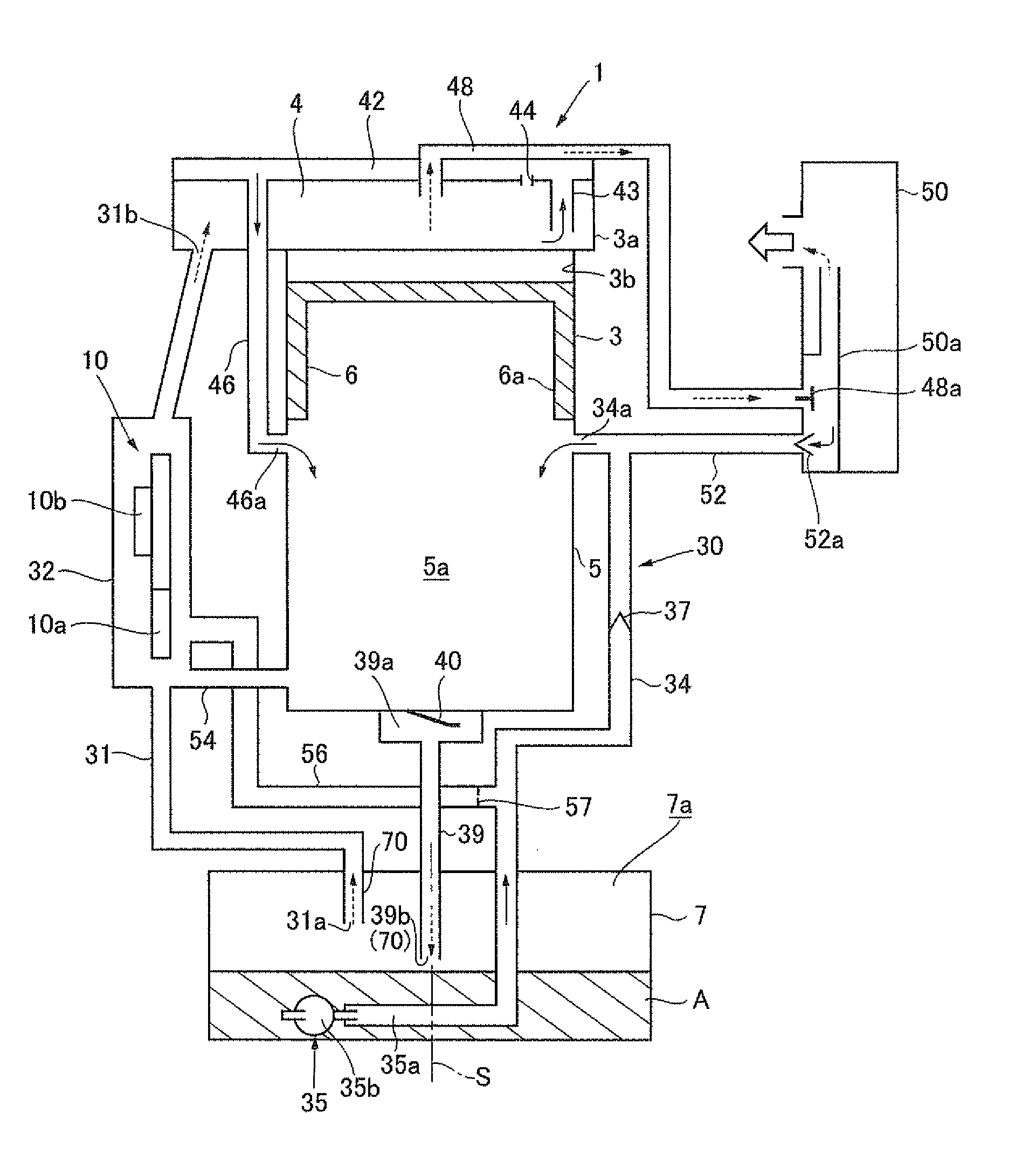
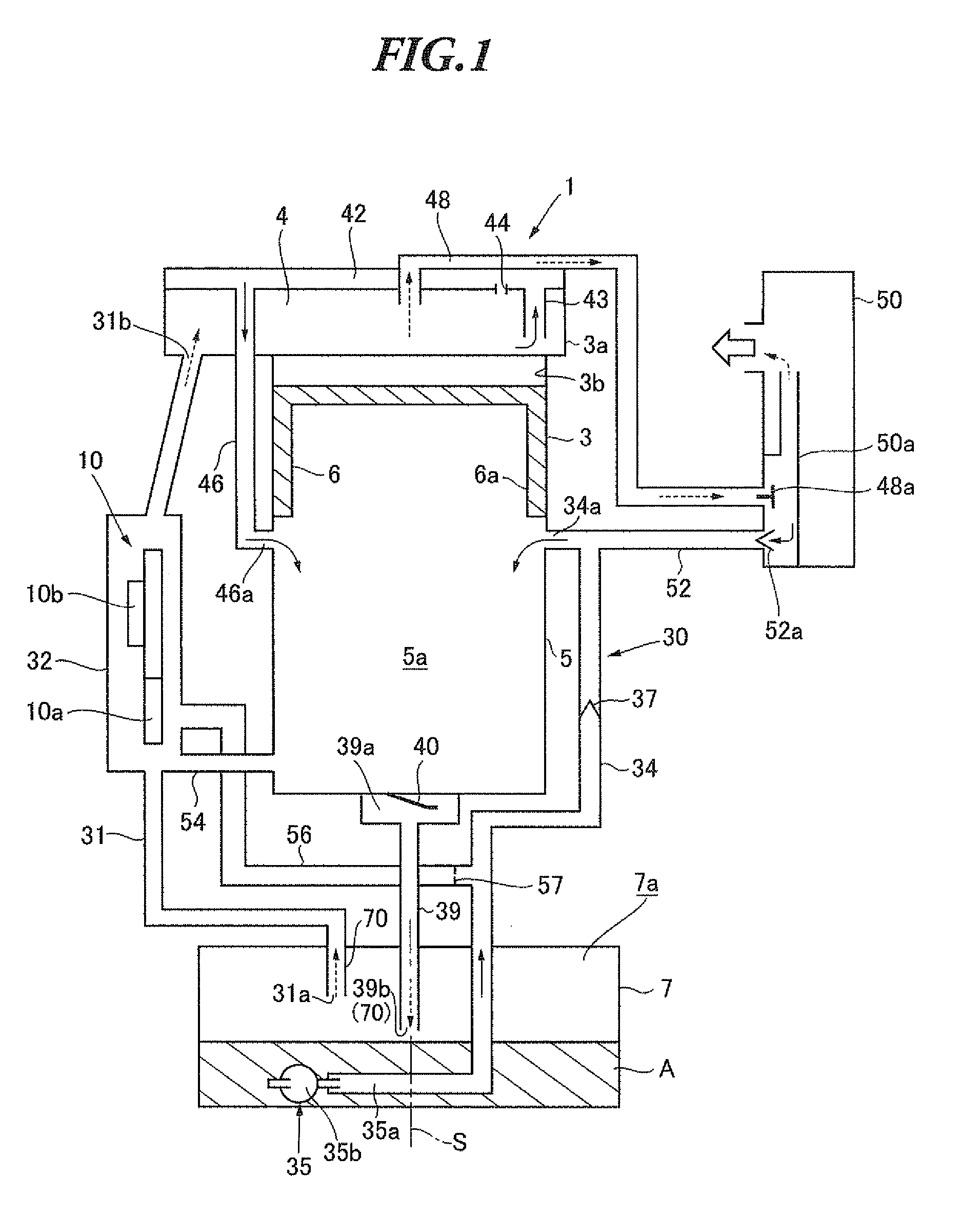
[0059]Hereinafter, one of preferred embodiments of a lubrication system for a four-stroke engine of the present invention will be described with reference to FIGS. 1 to 4. The lubrication system is installed in a four-stroke engine, and therefore a description will be given of the four-stroke engine equipped with the lubrication system with reference to FIG. 1 (schematic diagram). FIG. 1 shows the four-stroke engine when a piston is at the top dead center.

[0060]The four-stroke engine 1 (hereinafter referred to simply as “engine 1”) includes a cylinder block 3 integrated with a cylinder head 3a, a crank case 5 that is attached to the lower portion of the cylinder block 3 and forms a crank chamber 5a, and an oil reservoir 7 disposed below the crank case 5, as shown in FIG. 1. The oil reservoir 7 is provided separately from the crank case 5 and stores lubricating oil A (hereinafter referred to simply as “oil A”).

[0061]A crankshaft (not shown) is rotatably supported on the connection pa...

second embodiment

[0103]Hereinafter, another preferred embodiment of a lubrication system for a four-stroke engine of the present invention will be described with reference to FIGS. 5 and 6. The lubrication system is installed in a four-stroke engine, and therefore a description will be given of the four-stroke engine equipped with the lubrication system with reference to FIG. 5 (schematic diagram). FIG. 5 shows the four-stroke engine when a piston is at the top dead center.

[0104]The four-stroke engine 100 (hereinafter referred to simply as “engine 100”) includes a cylinder block 103 integrated with a cylinder head 103a, a crank case 105 that is attached to the lower portion of the cylinder block 103 and forms a crank chamber 105a, and an oil reservoir 107 disposed below the crank case 105, as shown in FIG. 5. The oil reservoir 107 is provided separately from the crank case 105 and stores lubricating oil A (hereinafter referred to simply as “oil A”).

[0105]A crankshaft (not shown) is rotatably support...


PUM


Abstract

A lubrication system for a four cycle engine that lubricates the valve mechanism with the oil mist of the concentration, lowered by the liquefying means. The lubrication system has an oil feeding passage for connecting an oil reservoir with the crank chamber and sending the oil retained in liquid form in the oil reservoir to the crank chamber under a negative pressure of the crank chamber, a communication passage for connecting the crank chamber with the oil reservoir and sending oil mist generated in the crank chamber to the oil reservoir when under a positive pressure of the crank chamber, liquefying means in the oil reservoir for liquefying the oil mist sent from the communication passage to the oil reservoir to decrease the concentration of the oil mist, and a supply passage for supplying the oil mist from the oil reservoir to the valve operating chamber through the liquefying means.

Description

FIELD OF THE INVENTION[0001]The present invention relates to a lubrication system for a four-stroke engine. More particularly, the invention relates to a lubrication system for a four-stroke engine in which no reduction in lubrication performance occurs even when the attitude of the engine is changed variously during use, and to a lubrication system for a four-stroke engine that can circulate oil for lubricating the engine even when the attitude of the engine is changed variously during use.BACKGROUND OF THE INVENTION[0002]Two-stroke engines are conventionally used as the driving engines of portable power tools, such as portable trimmers for trees and plants and backpack power tools, carried by the operators themselves or on the backs of the operators. However, for example, as awareness of environmental issues grows and emission regulations become more stringent, there is an increasing need for replacement of two-stroke engines used as driving sources with four-stroke engines.[0003]...

Claims


Application Information

Patent Timeline
Patent Type & Authority Patents(United States)
IPC IPC(8): F01M9/10F01M1/04F01M3/04
CPCF01M13/022F01M13/025F01M9/10F01M1/04F01M13/00F16N7/32F01M11/065F01M3/04
Inventor SUGIYAMA, MASAKITOMITA, TOSHIHIROKURIMOTO, MASAKIKUBOTA, HIROSHI
Owner MARUYAMA MFG CO INC
Why Eureka
Try Eureka