
Device for the sealed retention of a pipe, method for the sealed mounting of a pipe through a partition wall and use of such a device for the sealed penetration of a partition wall of an aircraft tank

a technology for sealing devices and pipes, applied in fluid pressure sealed joints, sleeve/socket joints, jet propulsion plants, etc., can solve the problem that the sealing no longer is able to effectively perform the required sealing function, and achieve the effect of reducing disadvantages

Active Publication Date: 2014-04-08
AMPHENOL AIR LB
View PDF20 Cites 7 Cited by
  • Summary
  • Abstract
  • Description
  • Claims
  • Application Information

AI Technical Summary

Benefits of technology

The patent text describes a device used to connect pipes. The device has rigid sections that keep the pipe in a set position and prevent the device from getting bent or deformed. This helps to ensure that the connection is secure and the device can perform its function effectively.

Problems solved by technology

However, when the assembly is intended to be used in an environment in which the mechanical stresses are relatively high, forces applied to the pipe tend to cause the seal to deform causing this seal no longer to be able effectively to perform the required sealing function and possibly, in certain extreme cases, pulling out of the orifice.
A situation such as this is unacceptable in applications for which the pipe retention function and the sealing function have to be performed effectively even in the event of severe mechanical forces.

Method used


Image

  • Device for the sealed retention of a pipe, method for the sealed mounting of a pipe through a partition wall and use of such a device for the sealed penetration of a partition wall of an aircraft tank
  • Device for the sealed retention of a pipe, method for the sealed mounting of a pipe through a partition wall and use of such a device for the sealed penetration of a partition wall of an aircraft tank
  • Device for the sealed retention of a pipe, method for the sealed mounting of a pipe through a partition wall and use of such a device for the sealed penetration of a partition wall of an aircraft tank

Examples


Embodiment Construction

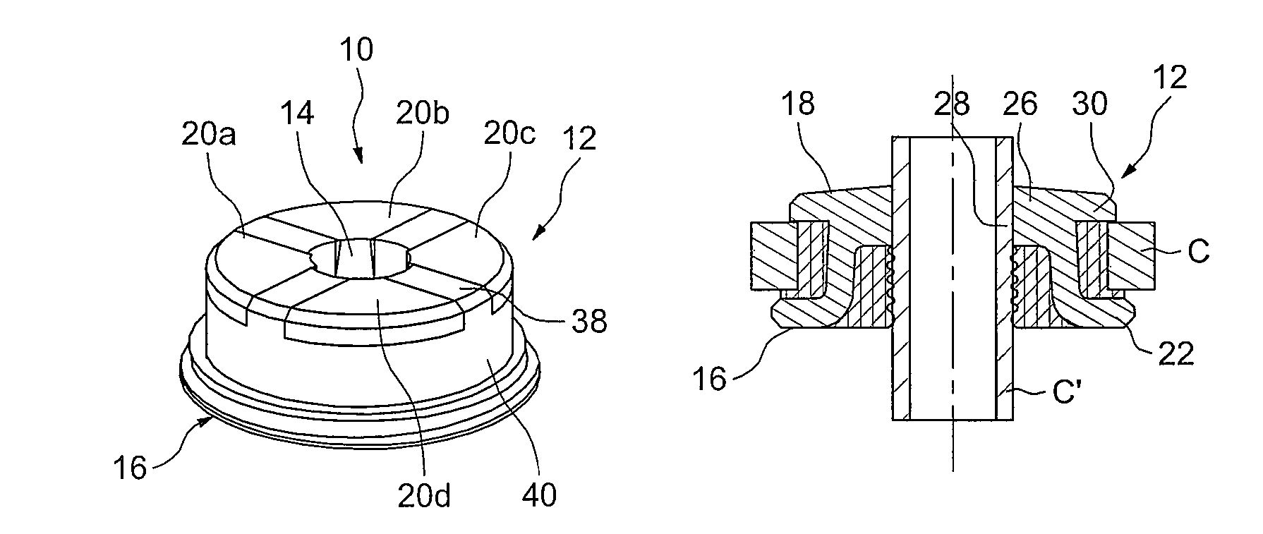
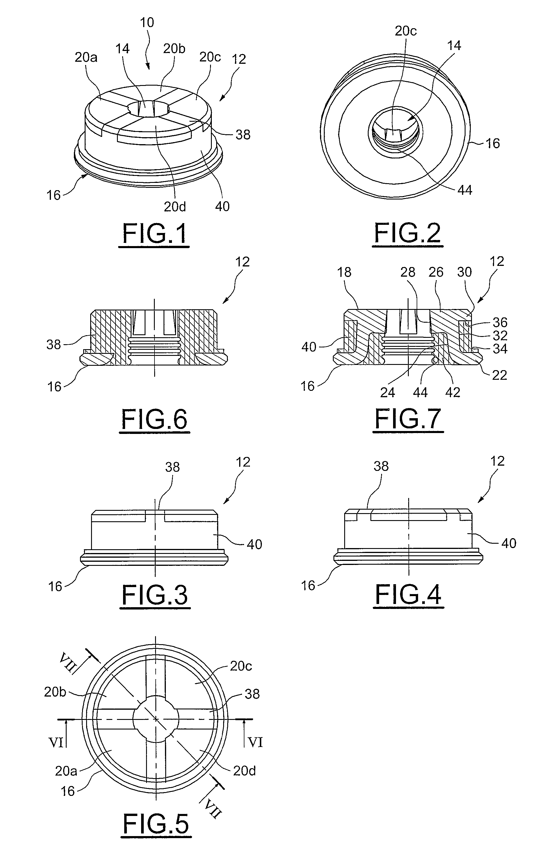
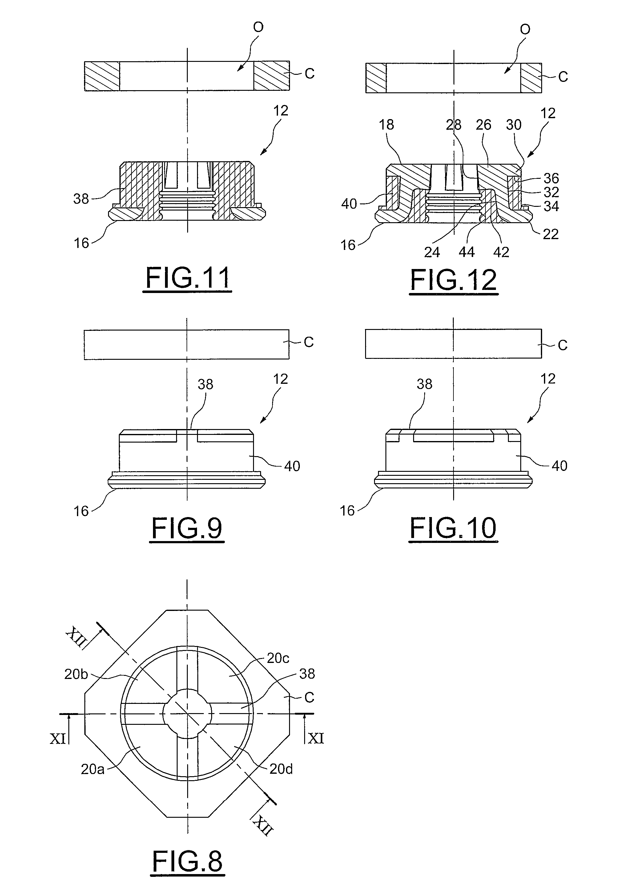
[0036]FIGS. 1 to 4 depict a device for the sealed retention of a pipe according to the invention, denoted by the overall numerical reference 10.

[0037]In the intended application, this device is intended to retain and seal a feed pipe passing through a partition wall of a kerosene tank carried on board an airplane.

[0038]However, it would not constitute a departure from the scope of the invention if the device were intended for the sealed mounting of a pipe or pipeline through other types of partition wall.

[0039]As may be seen, the device 10 has an annular overall shape, here of circular cross section.

[0040]It essentially comprises a body 12 provided with an axial passage 14 for the sealed passage of the pipe and with an annular flange 16. When considering the direction in which the pipe is introduced into the passage 14, the body 12 comprises a proximal end facing towards the flange 16 and an opposite distal end, of planar shape.

[0041]As will be described in detail hereinafter, the b...


PUM


Abstract

This device for the sealed retention of a pipe for the sealed penetration of a partition wall by the pipe comprises a body equipped with a sealed axial passage for the pipe and with a peripheral region for the sealed mounting of the device in an orifice made in the partition wall. The body comprises a set of rigid retaining sectors each comprising a bearing shoe for the pipe, and a sealing material positioned between the sectors to delimit the said sealed passage, and around the said sectors in the said peripheral region of the body via which region it is mounted on the partition wall.

Description

BACKGROUND OF THE INVENTION 1. Field of the Invention[0001]The invention deals in general with sealing devices and relates more specifically to the sealed mounting of a pipe through a partition wall.[0002]One particular advantageous application of the invention is the sealed penetration of a feed pipe through the wall of a fuel tank for an aircraft, particularly an airplane kerosene tank. 2. Description of the Relevant Art[0003]As will be appreciated, introducing a pipe through a partition wall entails making an orifice in the partition wall and generally involves the use of a seal inserted in the orifice. Conventionally, the seal is made of an elastically deformable material and has an axial passage into which the pipe is introduced and an annular peripheral groove in which the edge of the orifice made in the partition wall is inserted.[0004]The orifice is sized to ensure sufficient sealing between the pipe and the seal, as too is the annular groove which collaborates with the part...

Claims


Application Information

Patent Timeline
Patent Type & Authority Patents(United States)
IPC IPC(8): H02G3/22F16L21/02H02G3/18H02G15/013F16L5/02H02G15/04F16L17/00
CPCF16L5/10B60R16/0222B64D37/005F16L5/025F16L5/027Y10T137/0402
Inventor CAYZAC, GASPARD
Owner AMPHENOL AIR LB
Learn More