
Abating low-frequency noise using encapsulated gas bubbles

a technology of encapsulated gas and low-frequency noise, which is applied in the direction of instruments, machines/engines, transportation and packaging, etc., can solve the problems of affecting the migratory patterns of marine mammals, the exploration and drilling season, and the strategy is quite expensive, so as to facilitate the appropriate distribution of different gas-filed containers, facilitate the attachment of bubbles, and reduce the noise

Inactive Publication Date: 2014-04-08
BOARD OF RGT THE UNIV OF TEXAS SYST
View PDF8 Cites 10 Cited by
  • Summary
  • Abstract
  • Description
  • Claims
  • Application Information

AI Technical Summary

Benefits of technology

The patent describes a system for reducing underwater noise in various applications such as oil drilling, construction, and wind turbine installations. The system involves deploying an array of gas-filled containers designed to attenuate specific frequency ranges. The containers are attached to the sound source, such as an oil drilling ship or a military vessel, to control the noise in the emitted spectrum. The system can be flexible and cost-effective, using readily available components and little or no power. Overall, the patent provides a practical solution for reducing underwater noise and improving operational performance.

Problems solved by technology

For example, underwater acoustic noise from drilling ships in the Arctic is known to adversely affect the migratory patterns of marine mammals.
Governmental environmental regulations related to underwater noise limit the oil exploration and drilling season in this region to a small fraction of the year.
Once their presence is detected, communications are sent back to the ship and operations are halted, making this strategy quite expensive and further reducing the amount of time spent exploring and drilling.
Systems that use freely rising gas bubbles generally require the continuous supply of compressed air, which in turn requires operation of an air compressor, thus consuming energy and also radiating its own noise.
If the compressor is powered by a combustion engine, air pollution is created.
Furthermore, air supply lines are typically run from the compressor to the location of deployment, thus increasing capital and deployment costs.
Meanwhile, the use of air-filled, hard spherical shells has proven to be acoustically unsatisfactory for frequencies below 1000 Hz.
Also, due to their physical dimensions, air-filled hard spherical shell systems are expensive to transport and deploy in the field.

Method used


Image

  • Abating low-frequency noise using encapsulated gas bubbles
  • Abating low-frequency noise using encapsulated gas bubbles
  • Abating low-frequency noise using encapsulated gas bubbles

Examples


Embodiment Construction

[0058]It is to be understood the present invention is not limited to particular devices or methods, which may, of course, vary. It is also to be understood that the terminology used herein is for the purpose of describing particular embodiments only, and is not intended to be limiting. As used in this specification and the appended claims, the singular forms “a”, “an”, and “the” include singular and plural referents unless the content clearly dictates otherwise. Furthermore, the word “may” is used throughout this application in a permissive sense (i.e., having the potential to, being able to), not in a mandatory sense (i.e., must). The term “include,” and derivations thereof, mean “including, but not limited to.” The term “coupled” means directly or indirectly connected.

[0059]In some embodiments, the term “approximately” may refer to a value that is within 1% of another value. For example, a shell, container, or capsule having a resonance frequency of 101 Hz may be deemed to approxi...


PUM


Abstract

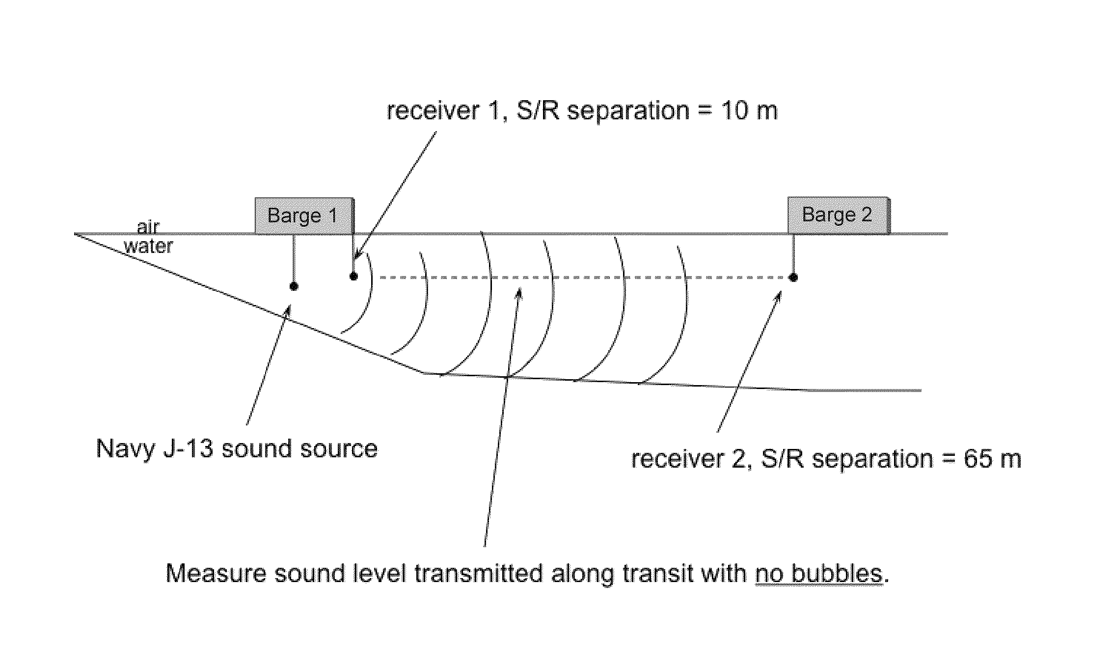
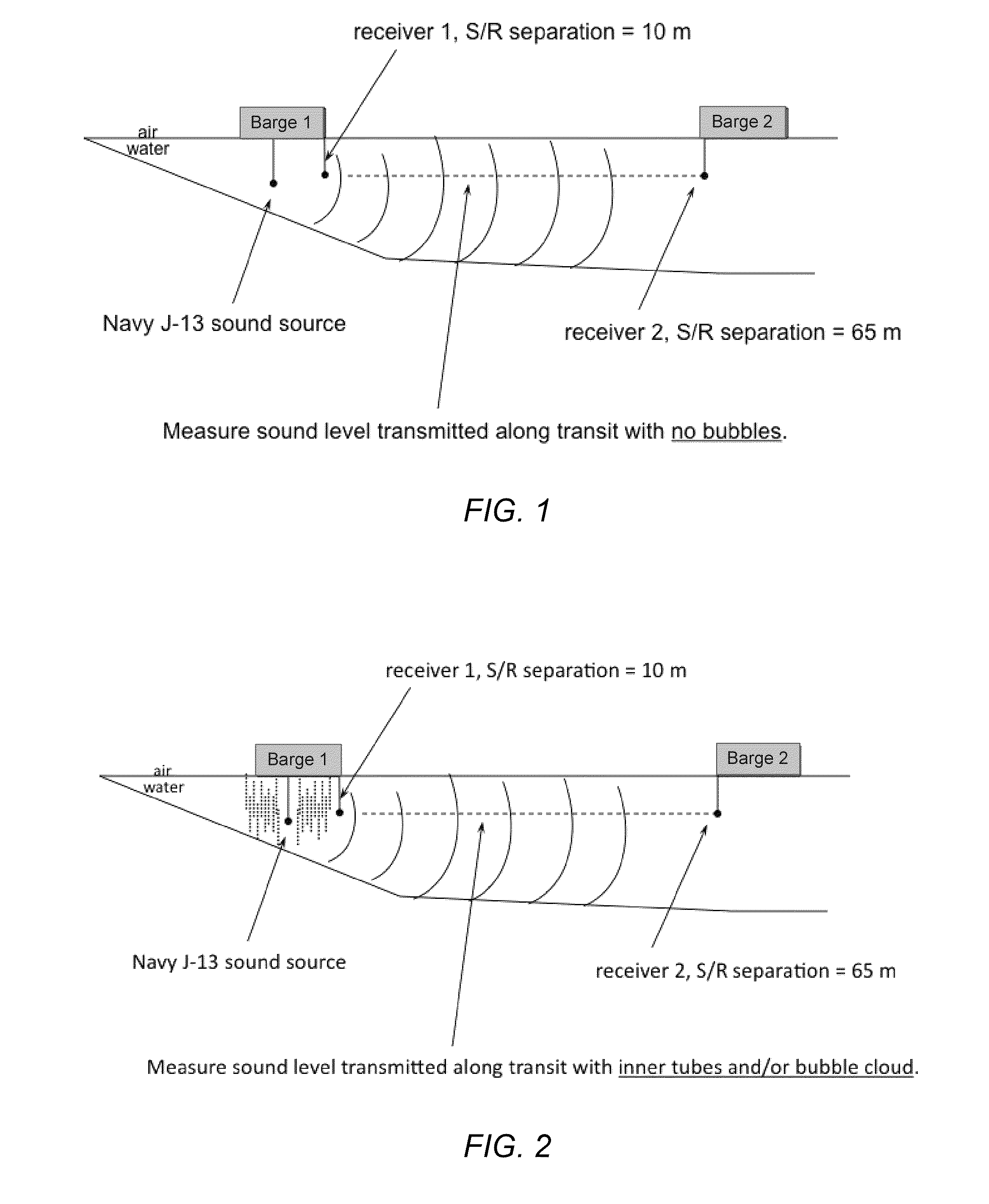
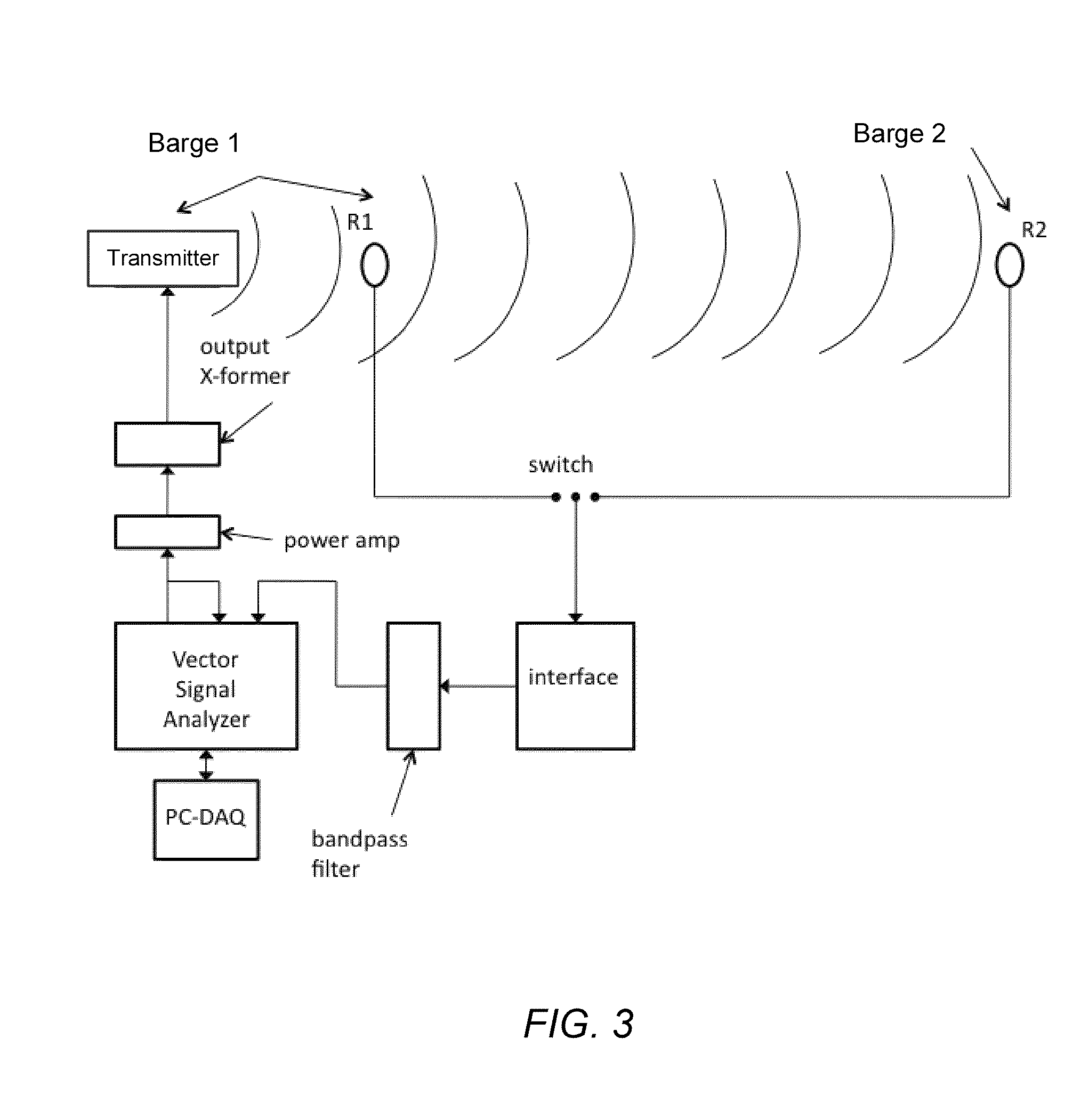
Air bubbles may be used to reduce radiated underwater noise. Two modalities of sound attenuation by air bubbles were shown to provide a reduction in radiated sound: bubble acoustic resonance damping and acoustic impedance mismatching. The bubbles used for acoustic resonance damping were manifested using gas-filled containers coupled to a support, and the acoustic impedance mismatching bubbles were created using a cloud of freely-rising bubbles, which were both used to surround an underwater sound source.

Description

PRIORITY CLAIM[0001]This application claims the benefit of U.S. Provisional Application No. 61 / 478,172 filed on Apr. 22, 2011.BACKGROUND OF THE INVENTION[0002]1. Field of the Invention[0003]The invention generally relates to a device capable of abating noise. More specifically, the device relates to reducing low frequency noise in an aquatic environment.[0004]2. Description of the Relevant Art[0005]Noise abatement techniques are often employed to satisfy environmental regulations, which are in place to protect marine life and habitat. For example, underwater acoustic noise from drilling ships in the Arctic is known to adversely affect the migratory patterns of marine mammals. Much of this noise occurs at low frequencies between 10 Hz and 200 Hz. Governmental environmental regulations related to underwater noise limit the oil exploration and drilling season in this region to a small fraction of the year. The current strategy for dealing with these regulations is a passive one in whic...

Claims


Application Information

Patent Timeline
Patent Type & Authority Patents(United States)
IPC IPC(8): F01N13/12
CPCF01N2590/02F01N1/065
Inventor WILSON, PRESTON S.LEE, KEVIN M.WOCHNER, MARK S.
Owner BOARD OF RGT THE UNIV OF TEXAS SYST
Learn More