Procedure for adaptive configuration recognition

a configuration recognition and configuration technology, applied in the field of adaptive configuration recognition, can solve the problems of increasing costs, unable to offer any advantages in regard to a fast and automatic adaptation of software, and the hardware components associated with the control device, such as actuators, sensors and other control devices, and achieve the effect of high computing power, especially simple and safe implementation of the procedure of the invention

Active Publication Date: 2014-04-01
ZF FRIEDRICHSHAFEN AG
View PDF23 Cites 2 Cited by
  • Summary
  • Abstract
  • Description
  • Claims
  • Application Information

AI Technical Summary

Benefits of technology

[0023]Accordingly, the invention emanates from a procedure for the adaptive configuration recognition of a vehicle, which possesses at least a central control unit that is connected via a data line with at least one additional component and which is further connected with at least one data memory unit in which the software to operate at least one central control device is securely stored against an unintended loss.
[0052]Another advantage of this procedure consists in error reporting only being generated and / or stored and / or processed for components that are considered to be present according to the procedure of the invention. Since a large number of error reports can normally be generated during frequent changes of components, this significantly eases searching for the cause upon the appearance of an actual error.

Problems solved by technology

At the same time the number of additional systems such as navigation and communication systems, in the vehicle and their networking to each other increases, which poses a variety of compatibility problems.
Because of the large number of different equipment variations in a vehicle from the production plant, the configuration of the control devices and the hardware components associated with them, like actuators, sensors and other control devices, represent a significant problem in the construction and design of a motor vehicle.
It is a disadvantage, however, that the software changes must be performed separately thereby increasing costs.
On the other hand, it does not offer any advantages with regard to a fast and automatic adaptation of the software configuration which depends on a hardware configuration that is present, since in the event of a component replacement, the current software parts must be externally placed in the memory component of the adapter.
A system with an external check of the hardware and software is not practical for vehicles that must be re-equipped periodically or even frequently and routinely.
An external reprogramming of control equipment after each conversion is neither practical nor justifiable, since the conversion times are to be kept as short as possible especially with regard to clearing operations.
The result is that the repeating of the registration must take place within very short time intervals and with corresponding greater stress on the entire system or the user runs the risk that after the deactivation of a component the vehicle will operate for a certain time without a current software configuration.
This is not only disadvantageous, but can also result in serious malfunctions or at least an unjustified error reporting, because of the various reciprocal effects between different hardware and software components.
Furthermore, it is not guaranteed that differentiation can be made between the intended removal of a component and a failure of the component.
The system is thus not able to react in a fully automatic manner to an upgrade, a conversion or another change in the configuration.
The solution of DE 199 26 206 C2 also is not suited for the fastest possible updating of the software-related, current configuration independent of the driver / operator.
This procedure, to be sure, facilitates the selective use of a component in various software modes, but it does not provide any indication of an integration of a replaced or added component into the system or the recognition of a configuration after the disassembly or addition of a component.
This, however, assumes the subsequent integration of the control device of the retarder, the hub drive and / or a change of the software or the parameters for operation, e.g., of the motor control system, and therefore often causes a costly new programming of other control devices or even an exchange of the central control device.

Method used


Image

  • Procedure for adaptive configuration recognition
  • Procedure for adaptive configuration recognition
  • Procedure for adaptive configuration recognition

Examples


Embodiment Construction

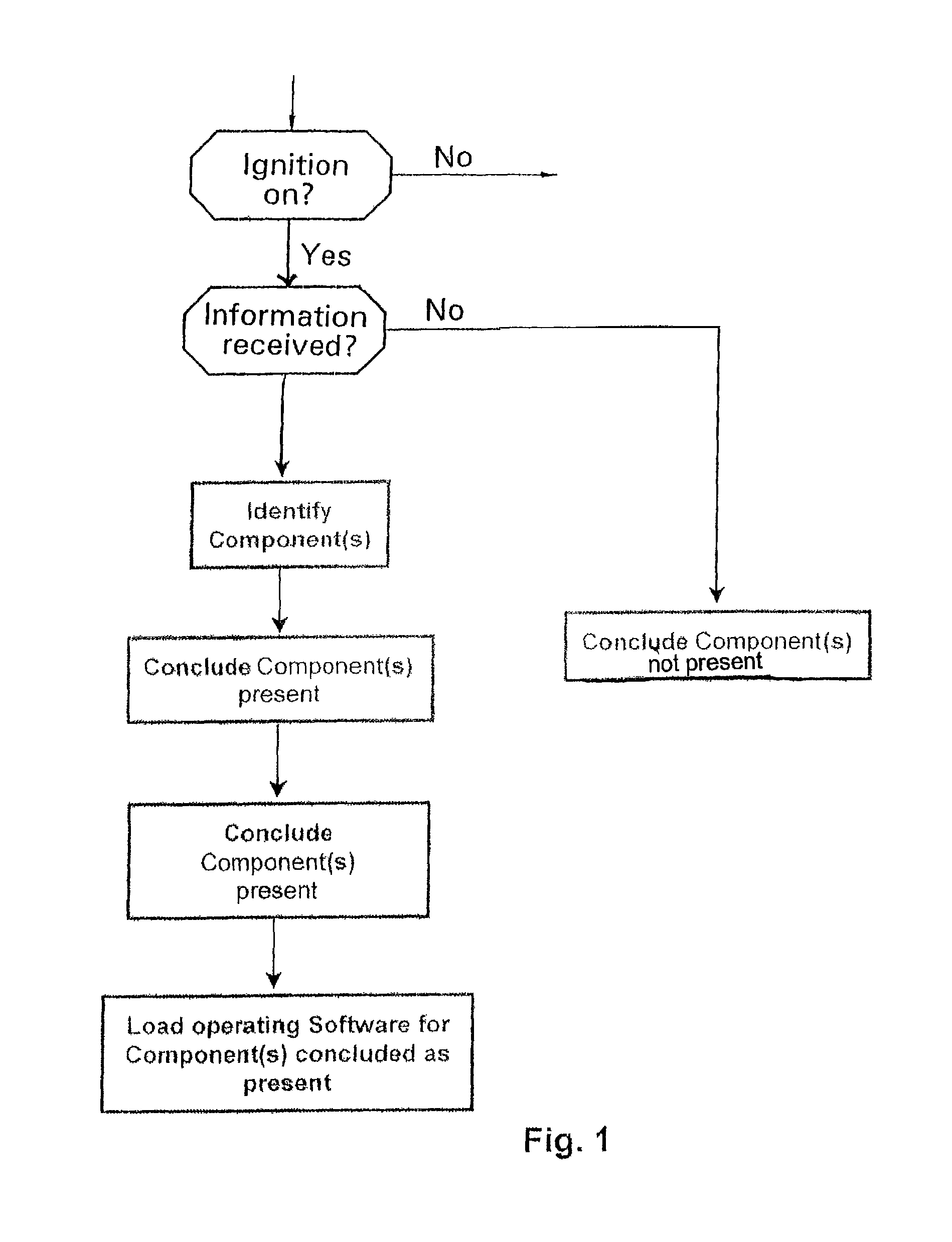
[0057]FIG. 1 assumes a truck is involved, which uses a procedure of the invention without storing the recognized configuration in a configuration memory area.

[0058]After turning on the vehicle ignition (sequential step: ignition on) and a run-up of the control device, there occurs a recognition of the vehicle configuration to the extent that the input information of the various components connected to each other and with the central control device, via a CAN, bus is evaluated. If the identifying information of certain components can be successfully read (sequential step: information present), it can be determined that these components are built into the vehicle network and are released for use (sequential step: components present). Accordingly, it is assumed that components are not built into the vehicle network or released if the appropriate information, for example the CAN bus messages or CAN bus signals, could not be read by the central control device (sequential step: components...


PUM


Abstract

The invention involves a procedure for adaptive configuration recognition after the run-up of a control device with or without configuration storage, which performs an automatic and operator-assisted, optimal configuration of the operating software of a motor vehicle.In a first variant, a central control device, after its run-up, receives at the earliest possible time, as a rule after activation of the ignition, identifying information from other components connected directly or indirectly to the central control device by data link. Upon receipt of the identifying information of a component, the central control device assumes that this component is present. Otherwise it assumes that it is not present. An additional configuration memory area is envisioned in a second variant in which the central control device, after the first receipt of the identifying information of a component, stores either the information, the associated software parts, or the software configuration resulting from the total of the recognized components. In this way, the appropriate software configuration can be quickly made available upon the new start of the vehicle with an unchanged hardware configuration. Furthermore, the procedure facilitates a guarantee that no error reports will be generated about components that are not present.

Description

[0001]This application claims priority from German Application Serial No. 10 2007 010 763.5 filed Mar. 6, 2007.FIELD OF THE INVENTION[0002]This invention involves a procedure for adaptive configuration recognition after the run-up of a control device of a motor vehicle.BACKGROUND OF THE INVENTION[0003]Motor vehicles are increasingly being equipped with many complex electrical and electronic devices and functions. In place of a mechanically and / or manually activated actuator for operating the basic functions of the vehicle, there are a variety of control devices for monitoring and influencing certain components or functions of the vehicle in a typical modern motor vehicle. To do this, it is necessary for the different control devices to exchange data with each other.[0004]Thus there are at least one motor control device, a transmission control device and other control devices involved in the control of a drivetrain of a vehicle which, for example, improve tracking in critical driving...

Claims


Application Information

Patent Timeline
Patent Type & Authority Patents(United States)
IPC IPC(8): G01M17/00B60L1/00G06F17/00G06F19/00
CPCG06F9/44542G05B2219/23345B60W2050/043G05B2219/25072G05B2219/25061G05B2219/2637B60W50/045G06F9/4411
Inventor JAGER, THOMASKALLER, MARIO
Owner ZF FRIEDRICHSHAFEN AG
Why Eureka
Try Eureka