
Ball and piston rotary actuator mechanism

a rotary actuator and piston technology, applied in the direction of gearing, manufacturing tools, hoisting equipment, etc., can solve the problems of limiting the range of motion of the attached arm, prone to damage, and rotary stroke less than 360 degrees

Active Publication Date: 2014-04-01
KRAFT BRETT W
View PDF6 Cites 4 Cited by
  • Summary
  • Abstract
  • Description
  • Claims
  • Application Information

AI Technical Summary

Benefits of technology

The present invention is a compact actuator mechanism that can rotate more than 360 degrees, and can be used in high-pressure environments and with very precise movements. It has the advantage of being hydraulically locked in position without leakage and can control movement precisely, without compression or stretch. The actuator can also operate under high external pressure conditions and may have the advantage of being lockable in position. Overall, it is stiff and precise in movement and can provide better control and efficiency for users.

Problems solved by technology

Often such robotic arms are utilized in environments which are dangerous or hazardous to humans, such as deep sea construction or exploration, chemical or explosives handling, outer space construction and the like.
One problem with such an arrangement is that one set of cylinders typically projects from the end of the arm.
In some situations, such projecting cylinders can limit range of motion of the attached arm and are also vulnerable to damage by unintended contact with other structures.
A problem with vane motors is a rotary stroke of less than 360 degrees because of space taken up by the fixed and movable vanes.

Method used


Image

  • Ball and piston rotary actuator mechanism
  • Ball and piston rotary actuator mechanism
  • Ball and piston rotary actuator mechanism

Examples


Embodiment Construction

[0026]As required, detailed embodiments of the present invention are disclosed herein; however, it is to be understood that the disclosed embodiments are merely exemplary of the invention, which may be embodied in various forms. Therefore, specific structural and functional details disclosed herein are not to be interpreted as limiting, but merely as a basis for the claims and as a representative basis for teaching one skilled in the art to variously employ the present invention in virtually any appropriately detailed structure.

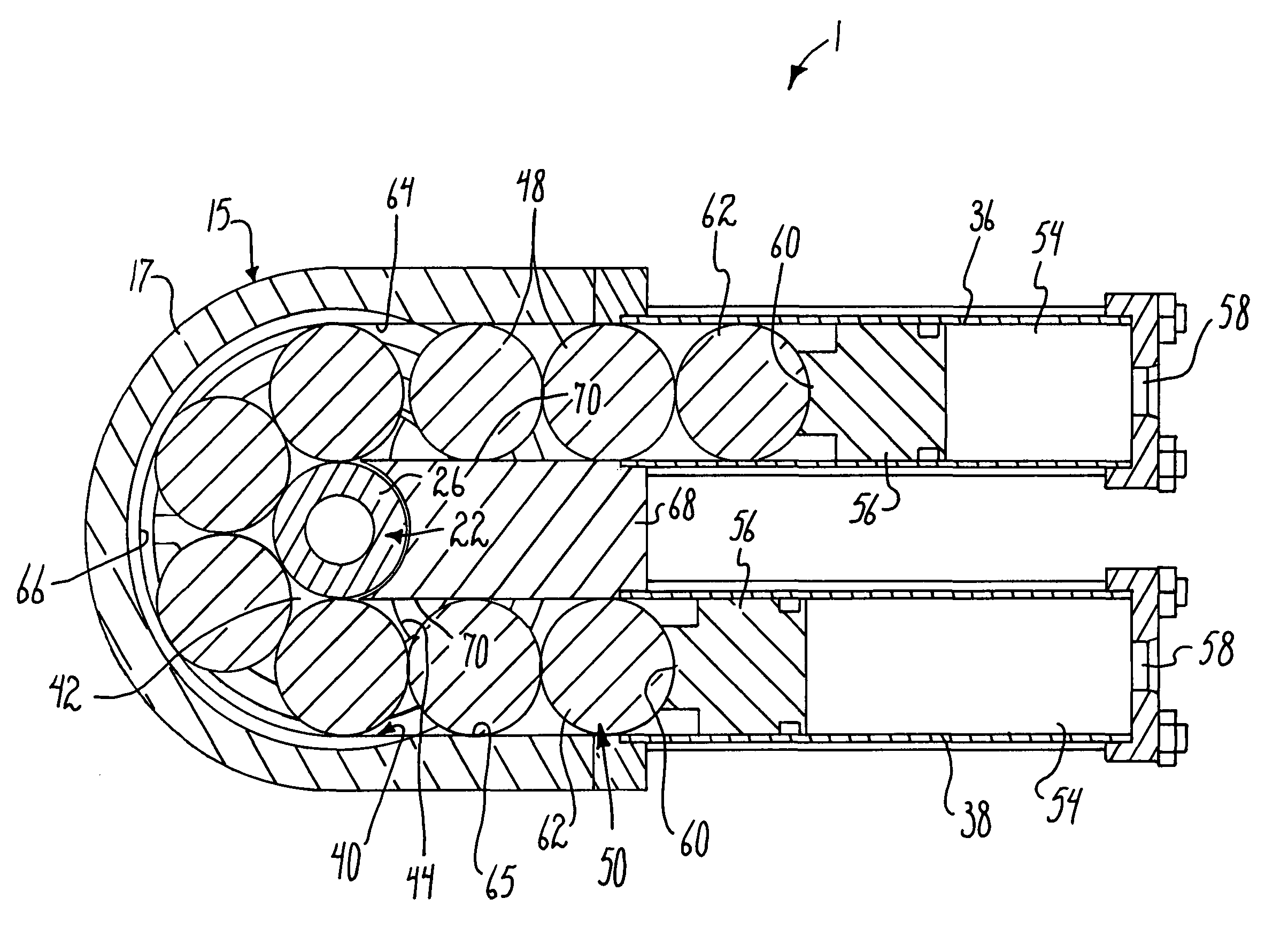
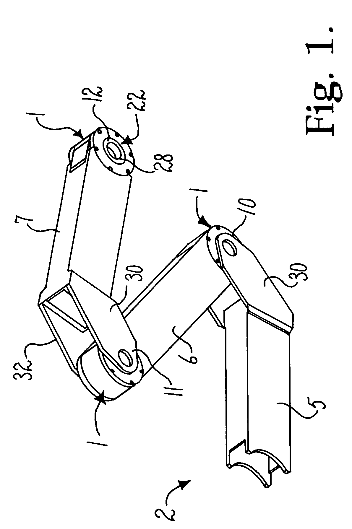
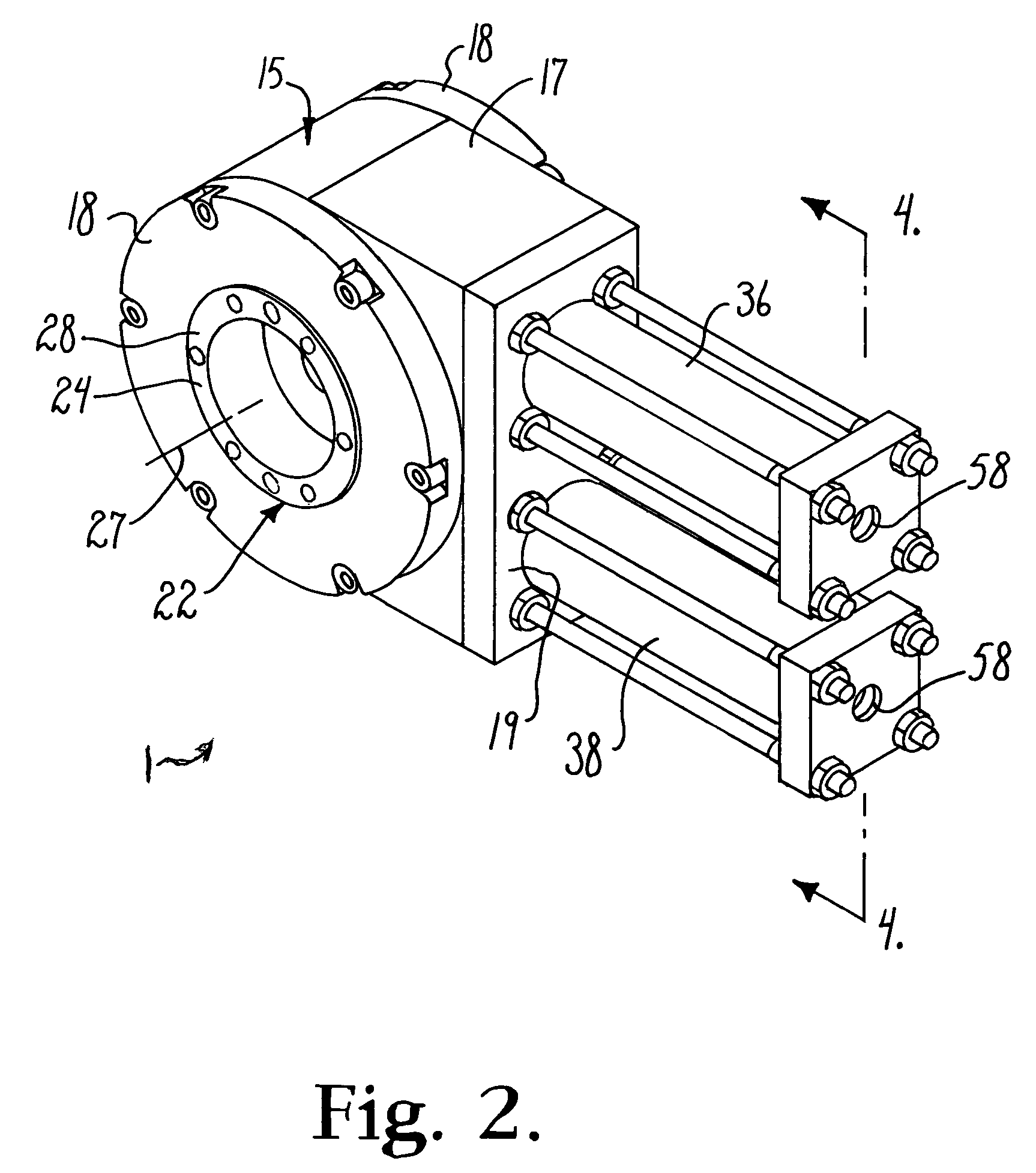
[0027]Referring to the drawings in more detail, the reference numeral 1 (in FIGS. 1-11) generally designates an embodiment of a ball and piston rotary actuator mechanism according to the present invention. The mechanism 1 is controlled to cause relative pivoting between structures interconnected by the mechanism 1, such as between components of a robotic arm assembly 2 (FIG. 1).

[0028]The illustrated robotic arm assembly 2 includes a base link or base 5 to whi...


PUM


Abstract

A rotary actuator mechanism for applying torque to a shaft and comprising an actuator housing forming an actuator path that includes an actuator pinion rotatably supported in said housing and having said shaft secured thereto. The pinion having peripheral notches of a selected shape and positioned within the actuator path. The mechanism having a train of discrete actuator elements having opposite ends and positioned in the actuator path, each of the actuator elements being of said selected shape to enable reception in the peripheral notches, a plurality of the elements engaging the notches. The mechanism having at least one linear actuator supported by the housing and engaging one of the ends of the train of actuator elements, the linear actuator being selectively activated to push the train of discrete actuator elements through the actuator path to thereby serially engage the actuator elements with the notches of the pinion and thereby apply torque to the shaft.

Description

CROSS-REFERENCE TO RELATED APPLICATIONS[0001]This application claims the benefit of U.S. Provisional Patent Application Ser. No. 61 / 279,853, filed Oct. 27, 2009 and incorporated by reference herein.BACKGROUND OF THE INVENTION[0002]The present invention is broadly directed to actuator mechanisms and, more particularly, to embodiments of a ball and piston rotary actuator mechanism using linear actuators to pivot a first structure relative to a second structure.[0003]Many robotic devices utilize robotic arms or arm like structures (herein generally referred to as arms) for conducting work at a site of use. Often such robotic arms are utilized in environments which are dangerous or hazardous to humans, such as deep sea construction or exploration, chemical or explosives handling, outer space construction and the like. An example of such use of robotic arms is described in U.S. Pat. No. 4,648,782, which is incorporated herein by reference.[0004]A robotic arm generally includes an elongat...

Claims


Application Information

Patent Timeline
Patent Type & Authority Patents(United States)
IPC IPC(8): F16H55/00
CPCF16H49/00F16H2019/0695F15B15/06F16H19/0622B25J9/146Y10T74/1884Y10T74/20329Y10T74/18568
Inventor KRAFT, BRETT, W.
Owner KRAFT BRETT W
Learn More