
Self-optimizing wireless network

a wireless network and self-optimization technology, applied in the field of wireless network planning and optimization, can solve the problems of consuming a large amount of human resources, affecting and affecting the coverage of the antenna as well as the interference that affects the coverage area of neighboring antennas

Active Publication Date: 2014-03-04
VIAVI SOLUTIONS INC
View PDF183 Cites 32 Cited by
  • Summary
  • Abstract
  • Description
  • Claims
  • Application Information

AI Technical Summary

Benefits of technology

The invention provides a method and system for optimizing a wireless network by analyzing network data and making changes to network parameters to improve communication. This can include evaluating network data to identify areas where communication is degraded, determining best neighbor cells to improve communication in those areas, and altering wireless network parameters to achieve the desired improvement in communication. This process can be repeated until the desired improvement is achieved. The system includes an optimization apparatus, controller, base station, controllable antenna, and dynamic load balancing apparatus. The technical effects of the invention include improved communication quality, reduced network traffic, and better user experience.

Problems solved by technology

Input power (i.e., the power sent from the base station or cell site) to the antenna will also affect the coverage of the antenna as well as the interference that impacts the coverage areas of neighboring antennas.
For example, if an antenna's input power is increased, the coverage area of the antenna may increase as well, thereby causing interference to the coverage area of a neighboring antenna and affecting the quality of service in that neighboring antenna's coverage area.
However, network planning and optimization consumes a high amount of human resources.
In addition, it is a lengthy process which is done only when needed or periodically with long periods between implementation.
In addition, because this process is manual and lengthy, it is conducted with low frequency, which results in leaving the network or parts of the network without optimization for long periods of time.
Thus, network resource usage is not maximized and unused available network resources result in significant revenue loss.
Finally, quality of service is degraded, which affects the end user's overall customer satisfaction.

Method used


Image

  • Self-optimizing wireless network
  • Self-optimizing wireless network
  • Self-optimizing wireless network

Examples


Embodiment Construction

[0025]In the description that follows, numerous details are set forth in order to provide a thorough understanding of the invention. It will be appreciated by those skilled in the art that variations of these specific details are possible while still achieving the results of the invention. Well-known elements and processing steps are generally not described in detail in order to avoid unnecessarily obscuring the description of the invention.

[0026]In the drawings accompanying the description that follows, often both reference numerals and legends (labels, text descriptions) may be used to identify elements. If legends are provided, they are intended merely as an aid to the reader, and should not in any way be interpreted as limiting.

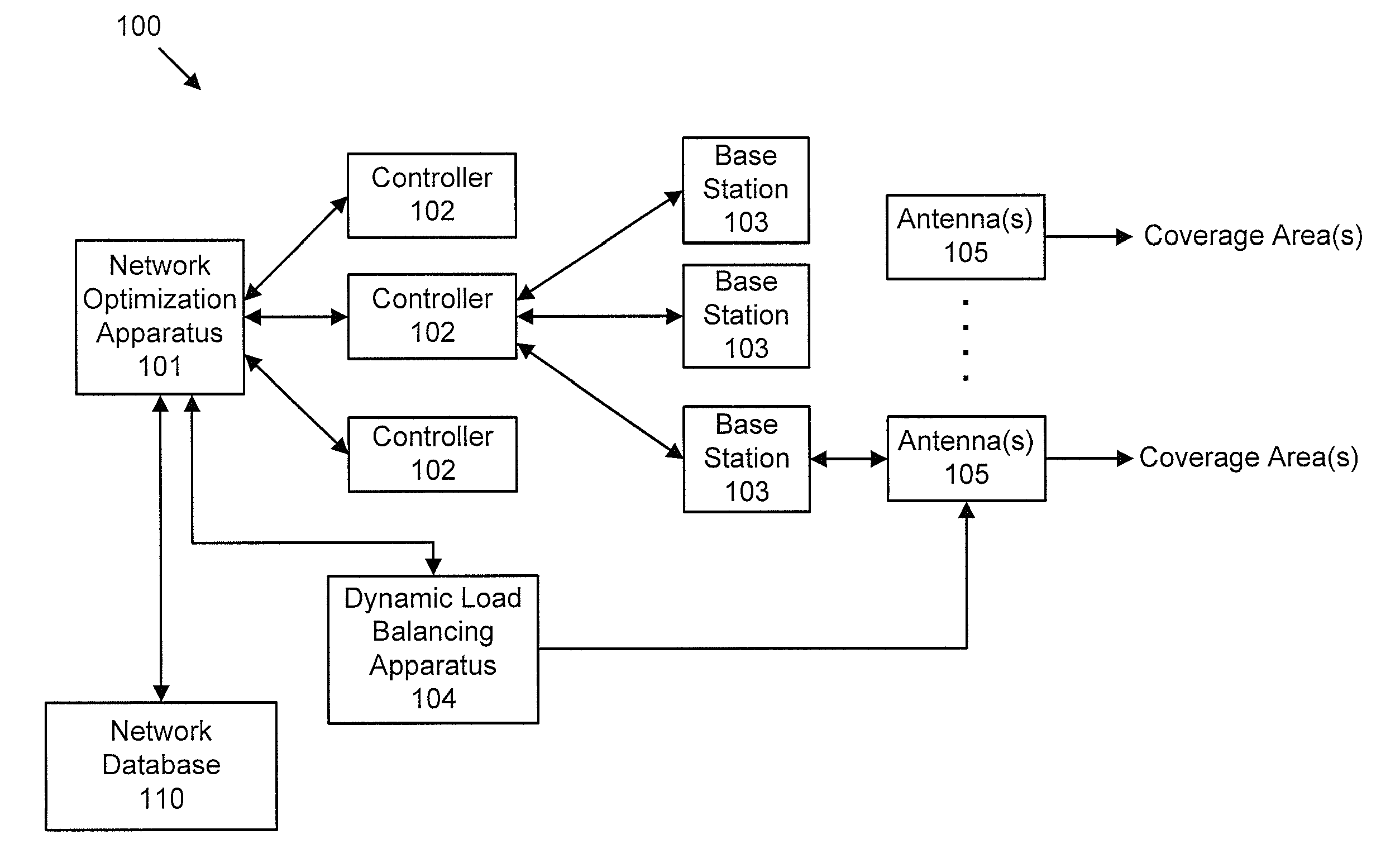
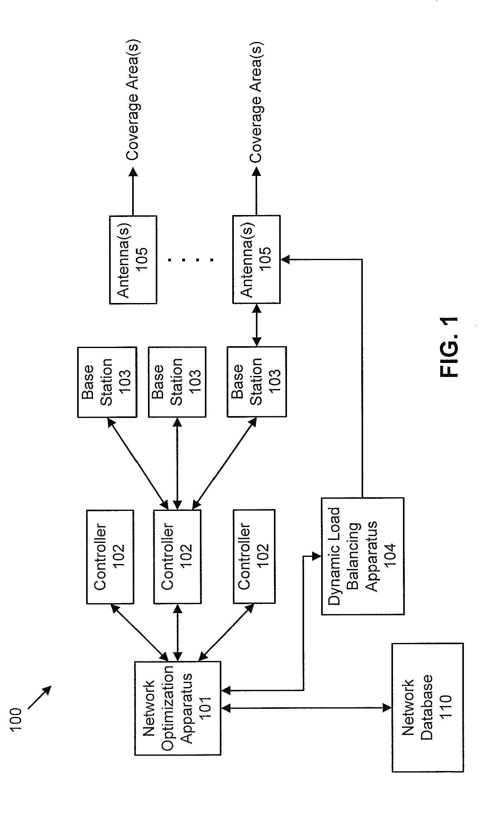
[0027]FIG. 1 is a system for optimizing of network parameters in a wireless network in accordance with an embodiment of the invention. In particular, the wireless network 100 illustrated in FIG. 1 includes a network optimization apparatus 101. The wireles...


PUM


Abstract

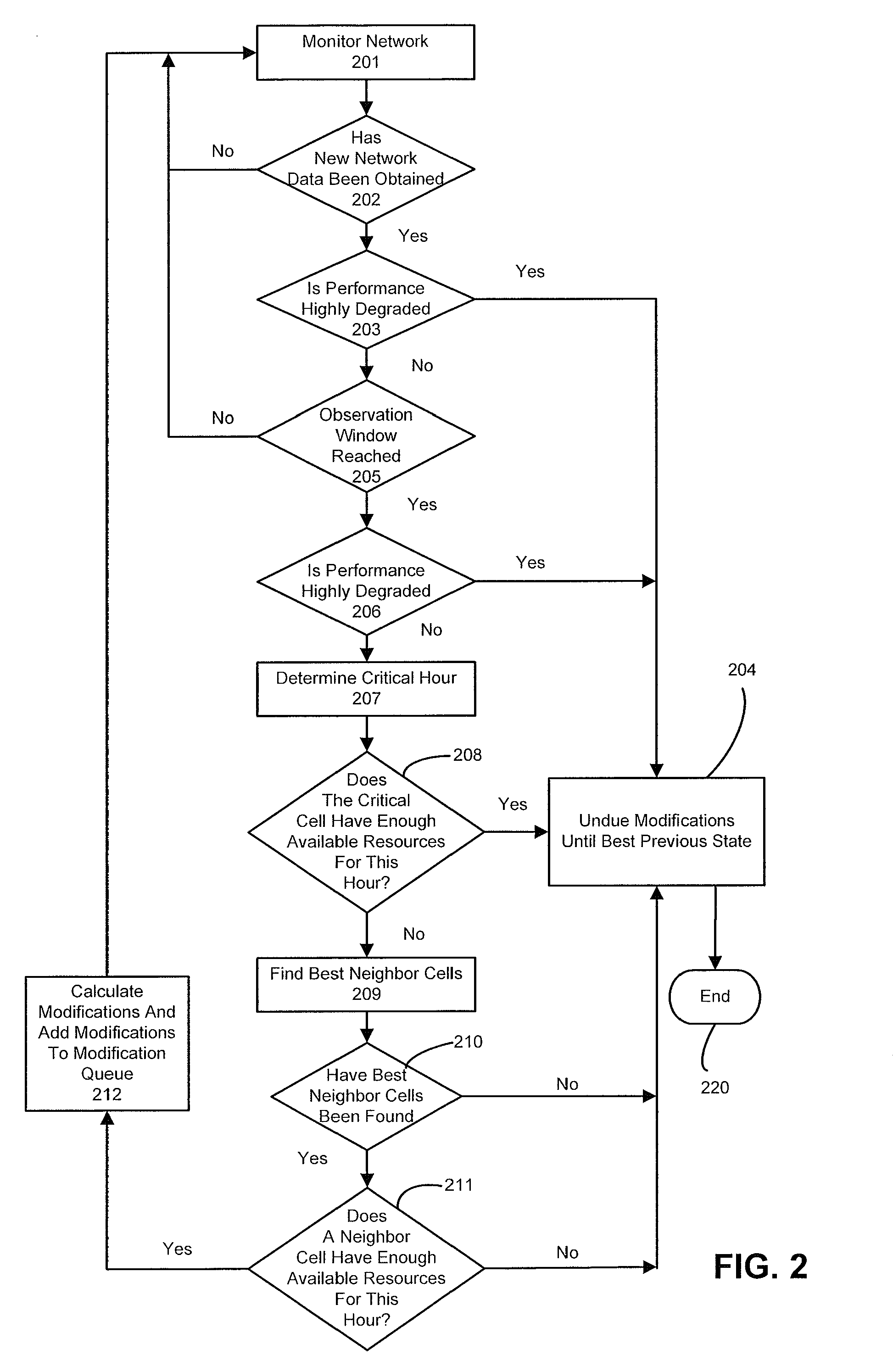
Optimizing a plurality cell sites or sectors in a wireless network including receiving network data regarding a plurality of cell sites or sectors; determining a critical zone in which communication is degraded; determining best neighbor cell sites or sectors among the neighbor cell sites or sectors associated with the critical cell sites or sectors; determining if the critical cell sites or sectors in the critical zone have available resources for achieving a desired improvement in communications; determining if the best neighbor cell sites or sectors have available resources for achieving the desired improvement in communications; and altering wireless network parameters of the critical cell sites or sectors, or the best neighbor cells sites or sectors for achieving the desired improvement in communications.

Description

CROSS-REFERENCE TO RELATED APPLICATION[0001]This application is a continuation of U.S. patent application Ser. No. 12 / 580,604, filed Oct. 16, 2009, and entitled “Self-Optimizing Wireless Networks,” which is incorporated herein by reference in its entirety.BACKGROUND OF THE INVENTION[0002]1. Field of the Invention[0003]The present invention generally relates to planning and optimization for a wireless network. In particular, the present invention relates to a system that monitors network performance, and makes changes to network parameters to enhance performance.[0004]2. Description of the Related Art[0005]Network planning of a wireless network relies on static approaches for site locations and dimensioning of the radio resources to meet specified traffic demand at busy hours. In a wireless network, a large number of base stations (i.e., cell sites) can be served by one or more antennas. The base station hardware will send a radio frequency signal to the antennas, which will typicall...

Claims


Application Information

Patent Timeline
Patent Type & Authority Patents(United States)
IPC IPC(8): H04W4/00
CPCH04W24/02H04W16/18H04W72/04
Inventor HUSSEIN, OSAMAHAFEDH, TRIGUI
Owner VIAVI SOLUTIONS INC
Learn More