
Bowstring cam arrangement for compound crossbow

a crossbow and cam arrangement technology, applied in the field of compound bows, can solve problems such as difficult to achieve goals, and achieve the effects of reducing mechanical losses, improving efficiency, and increasing energy transfer

Active Publication Date: 2014-02-18
RAVIN CROSSBOWS
View PDF30 Cites 94 Cited by
  • Summary
  • Abstract
  • Description
  • Claims
  • Application Information

AI Technical Summary

Benefits of technology

The compound bow or crossbow described in this patent has a unique design that reduces the number of cam wheels and pulleys, resulting in greater efficiency and higher transfer of energy from the bow to the arrow. This design also allows for faster acceleration of the bolt or arrow throughout the travel of the bowstring, resulting in significantly higher velocity.

Problems solved by technology

These goals have been difficult to achieve.
Some inefficiencies are due to mechanical losses in the crossover strings and pulley mechanisms.

Method used


Image

  • Bowstring cam arrangement for compound crossbow
  • Bowstring cam arrangement for compound crossbow
  • Bowstring cam arrangement for compound crossbow

Examples


Embodiment Construction

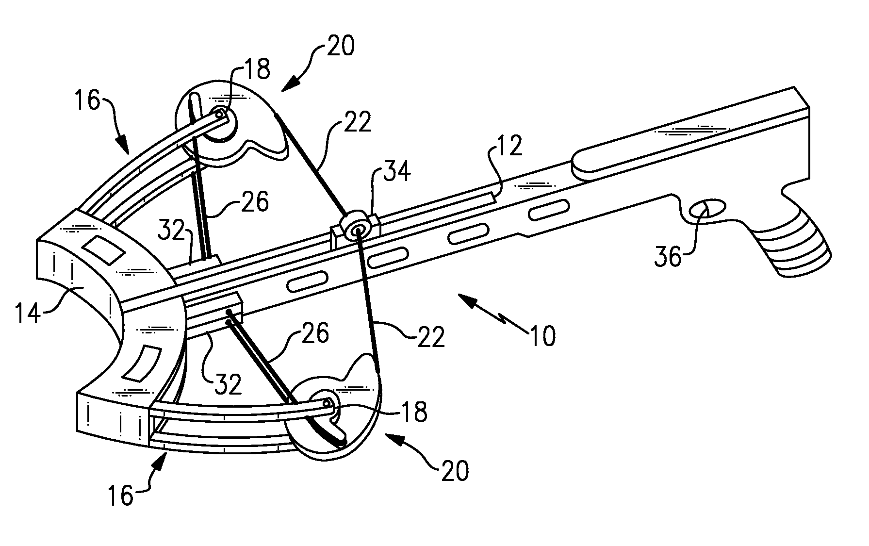
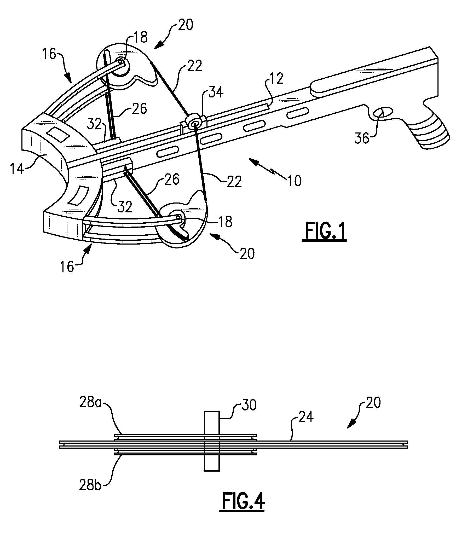
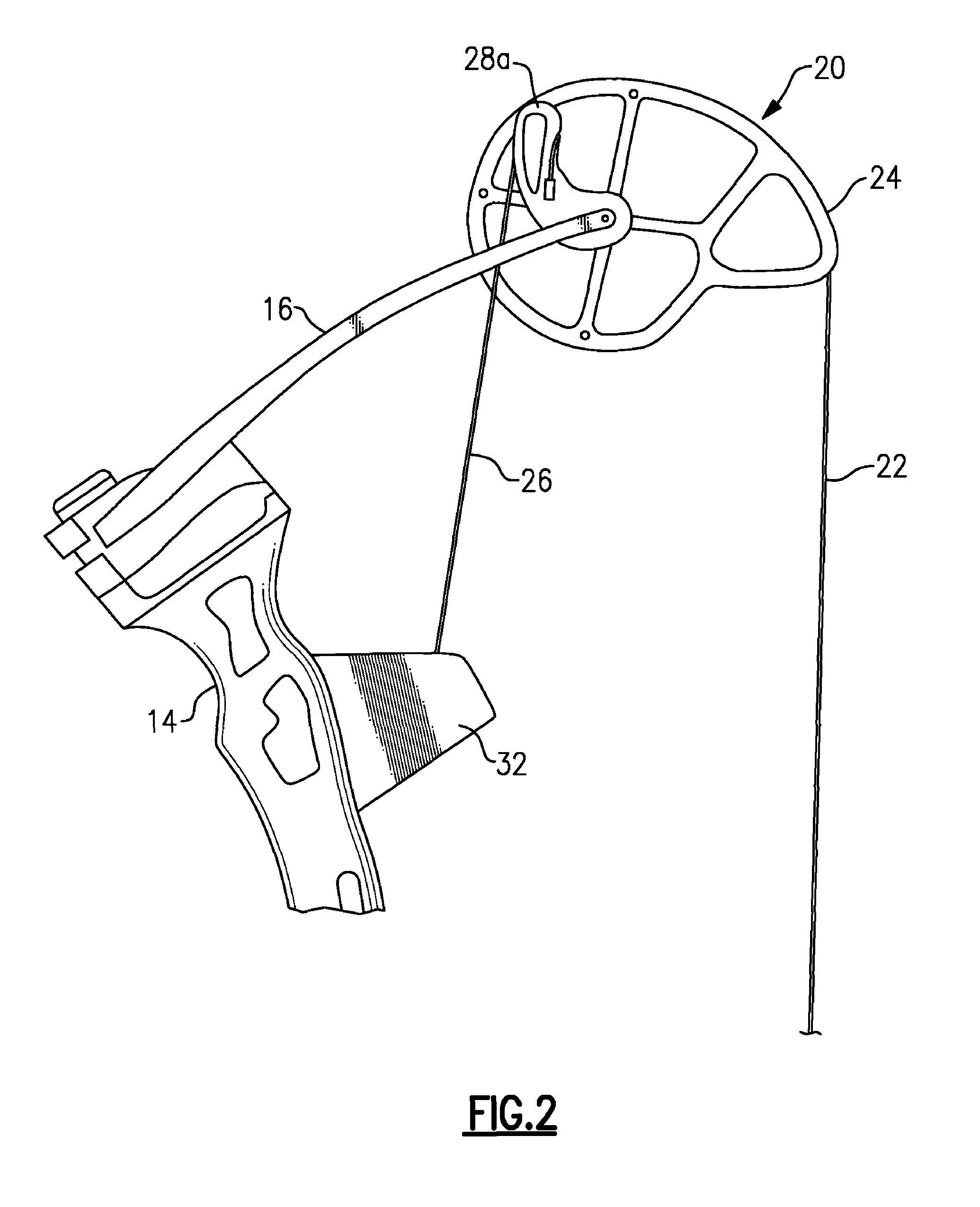
[0011]The invention is explained in terms of a possible preferred embodiment, here a crossbow 10, in which there is an axial beam or stock 12 defining a medial plane with a riser 14 extending transversely at a front or distal end thereof. At each end of the riser 14 there is a power limb or spring limb 16, i.e., a spring limb at the right end of the riser and one at the left end. Each spring limb 16 has one end anchored to the riser and at its other end a pivot 18 in which a respective cam wheel 20 is supported. In this embodiment, the spring limbs 16 are formed of an upper portion and a lower portion, with the cam wheel 20 held in between them.

[0012]Note that in a crossbow, the riser extends horizontally or transversely, while in a long bow the riser extends vertically. The mechanics of operation are the same in either orientation.

[0013]A bow string 22 is attached to each bowstring cam 20 and rides in a peripheral bowstring groove or channel 24 in each of these cams. In this invent...


PUM

PropertyMeasurementUnit
flexibleaaaaaaaaaa
weightaaaaaaaaaa
pull weightaaaaaaaaaa

Abstract

A compound bow or crossbow employs bowstring cams with bowstring cam grooves and power cord cam grooves. Preferably a pair of generally identical power cord cam grooves are positioned axially above and below the bowstring cam groove. The power cords are anchored to a fixed anchor point, e.g., a pylon, on the near end of the riser or on the near side of the crossbow bar or stock. The power cords do not cross over to the other limb. The reduction in the number of cam wheels and pulleys and in the number of strings or cords results in greater efficiency and higher transfer of energy from the bow to the arrow or bolt. There is no drop-off in pull weight at full draw. The bolt or arrow accelerates throughout the travel of the bowstring, resulting in significantly higher velocity.

Description

[0001]Applicant claims priority under 35 U.S.C. §119(e) of Provisional Application Ser. No. 61 / 356,109, filed Jun. 18, 2010.BACKGROUND OF THE INVENTION[0002]This invention is directed to the field of archery, and more specifically to compound bows of the type employing cams and control cables to achieve a programmed draw weight, and the latter being variable with draw length. Applicant incorporates by reference prior U.S. Pat. No. 6,776,148 and other patents referred to in that document, that is, archery bows that have cams and power cords, and are programmed for optimal draw weight characteristics.[0003]Typically, compound bows have means to regulate their draw weight so that a maximum pull weight is attained at an intermediate draw position, and with the draw weight dropping to some fraction of maximum pull weight at the full draw position.[0004]It is also an objective of modern bows and crossbows to transfer to the bolt or arrow as much as possible of the energy that is stored in...

Claims


Application Information

Patent Timeline
Patent Type & Authority Patents(United States)
IPC IPC(8): F41B5/10F41B5/14F41B5/12
CPCF41B5/123Y10S124/90F41B5/10F41B5/105Y10T29/49826
Inventor ISLAS, JOHN, J.
Owner RAVIN CROSSBOWS
Learn More