
Method and apparatus for estimating a channel quality indicator (CQI) for multiple input multiple output (MIMO) systems

a channel quality indicator and multi-input technology, applied in the field of communication systems, can solve problems such as inability to transmit information, receivers are unable to correctly reconstruct transmitted information, and corrupt signals, and achieve the effect of effective signal-to-noise ratio (snr) valu

Active Publication Date: 2014-02-04
NXP USA INC
View PDF2 Cites 90 Cited by
  • Summary
  • Abstract
  • Description
  • Claims
  • Application Information

AI Technical Summary

Benefits of technology

The patent describes systems and methods for determining the quality of a transmission channel in a transmission system. It involves identifying multiple independent branches that correspond to different parts of the effective channel. These branches are then combined to create a single value that indicates the overall quality of the transmission. This helps to improve the reliability and quality of the transmission.

Problems solved by technology

The medium, or media, between the transmitter and receiver, through which the information is sent, may corrupt the signal such that the receiver is unable to correctly reconstruct the transmitted information.
However, the transmitter may be unaware of how the channel will affect a transmitted signal, and may not be able to transmit information in a way that will be effective for a particular channel.
However, transmit diversity schemes may present various challenges to estimating CQI using these conventional methods.
For example, in some transmit diversity schemes, the channel state information may be limited or inaccurate, and portions of the communication channel may not be available or may be too complex to compute or manipulate.
In some transmit diversity schemes, effective channels may experience fast fading in the time domain or large frequency selective fading in the frequency domain, rendering the conventional CQI methods ineffective.

Method used


Image

  • Method and apparatus for estimating a channel quality indicator (CQI) for multiple input multiple output (MIMO) systems
  • Method and apparatus for estimating a channel quality indicator (CQI) for multiple input multiple output (MIMO) systems
  • Method and apparatus for estimating a channel quality indicator (CQI) for multiple input multiple output (MIMO) systems

Examples


Embodiment Construction

[0021]The present disclosure generally relates to estimating a channel quality indicator (CQI) in a transmission system. In particular, systems and methods are described for estimating CQI for multiple input multiple output (MIMO) systems that employ transmit diversity schemes. In one aspect, the CQI is estimated using multiple independent diversity branches that correspond to different portions of the effective transmission channel.

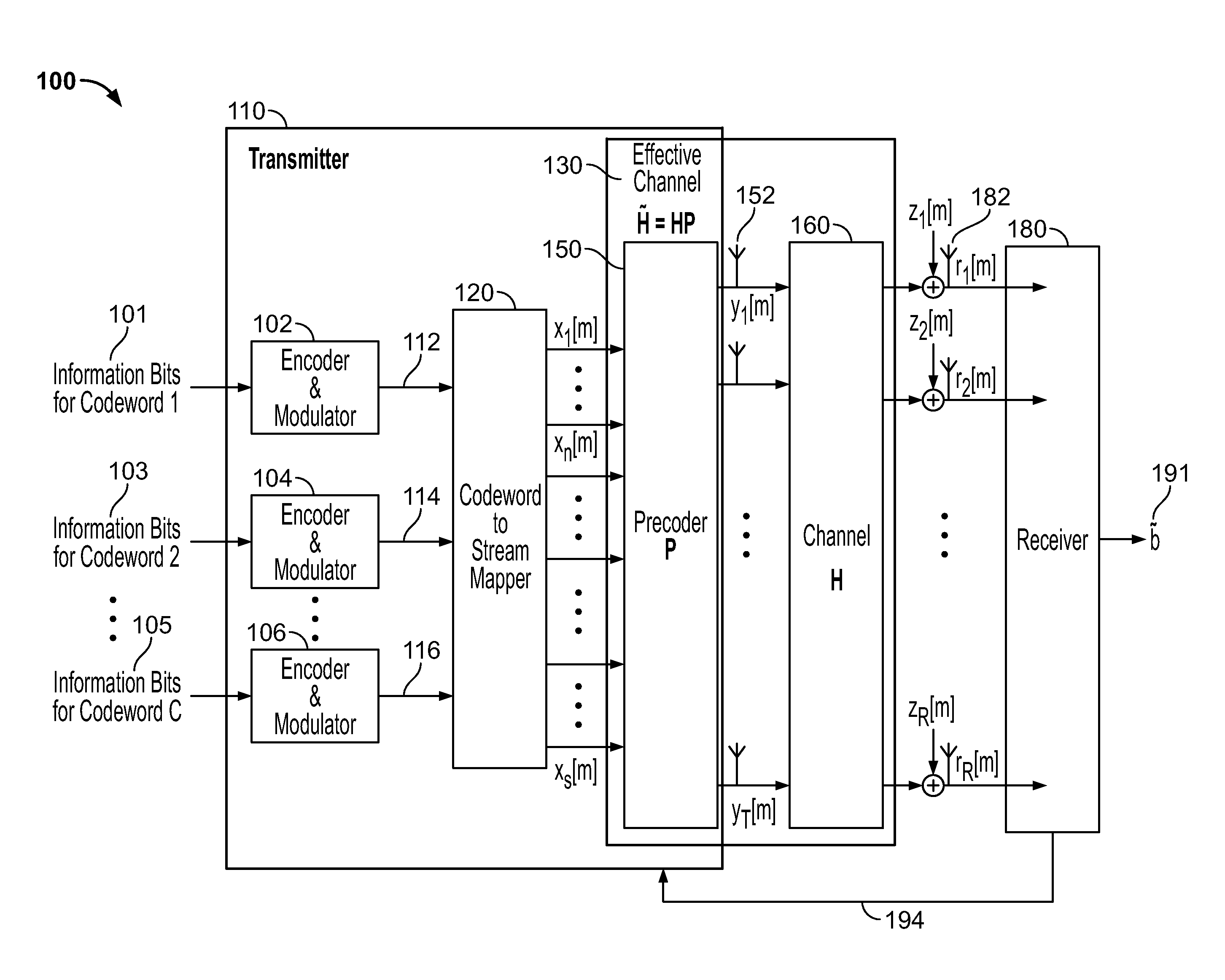
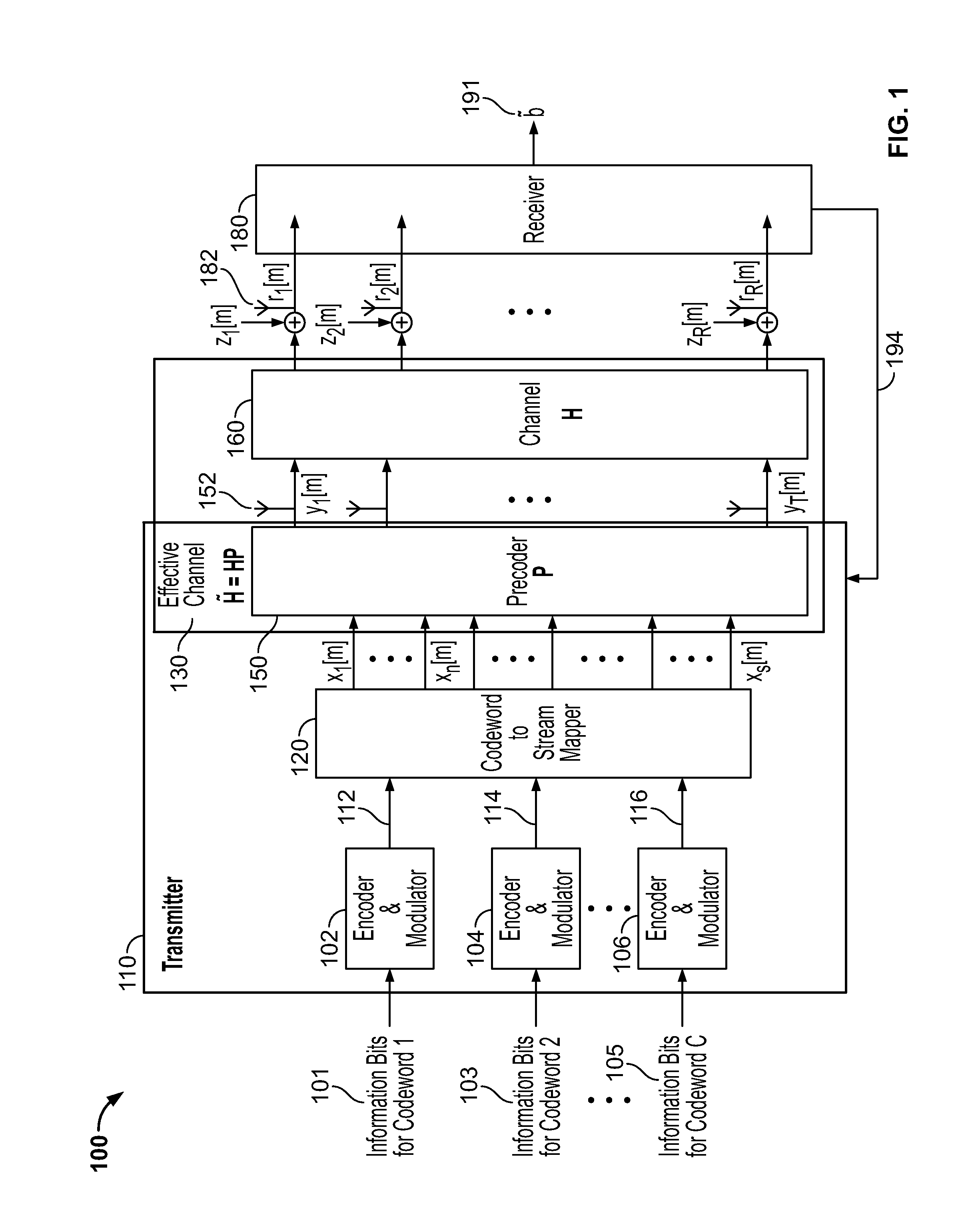
[0022]FIG. 1 shows an illustration of a data transmission system 100 in accordance with some embodiments. The system of FIG. 1 includes transmitter 110, channel 160, and receiver 180. In some embodiments, data to be transmitted may be divided between a large number of transmission systems such as system 100, where each system corresponds to one parallel transmission. For example, system 100 may correspond to one subcarrier that carries data in a particular frequency range, or a tone. In some embodiments, the illustrated system may represent a wireless co...


PUM


Abstract

Systems and methods are provided for determining a channel quality indicator (CQI) in a transmission system associated with a diversity transmission scheme. A plurality of independent diversity branches are identified in the diversity transmission scheme. Each one of the independent diversity branches may correspond to a different portion of the effective channel and may include any suitable combination of frequency, time, and / or spatial components of the effective channel or of any wired or wireless paths or combinations of the same. An effective Signal-to-Noise Ratio (SNR) value is computed for each one of the identified independent diversity branches. The computed effective SNR values are combined for the identified independent diversity branches to generate a CQI value.

Description

CROSS-REFERENCE TO RELATED APPLICATIONS[0001]This application claims benefit under 35 U.S.C. §119(e) of U.S. Provisional Application No. 61 / 346,828, filed May 20, 2010, which is hereby incorporated herein by reference in its entirety.BACKGROUND OF THE INVENTION[0002]The background description provided herein is for the purpose of generally presenting the context of the disclosure. Work of the inventors hereof, to the extent the work is described in this background section, as well as aspects of the description that may not otherwise qualify as prior art at the time of filing, are neither expressly nor impliedly admitted as prior art against the present disclosure.[0003]The disclosed technology relates to communication systems, and more particularly, to estimating a channel quality indicator (CQI) for multiple input multiple output (MIMO) systems that use transmit diversity schemes.[0004]In a data transmission system, it is desirable for information, often grouped into packets, to be...

Claims


Application Information

Patent Timeline
IPC IPC(8): H04W4/00
CPCH04L1/0036H04L1/06H04B17/0067H04B7/0671H04B7/0673H04B7/0413H04W4/00H04B7/0632H04B7/066H04L1/0029H04B7/068H04B7/0691H04B7/0456H04L5/0023H04L1/0026H04B7/0678H04B17/006H04B17/336
Inventor SUN, YAKUNMATACHE, ADINALEE, JUNGWON
Owner NXP USA INC
Learn More