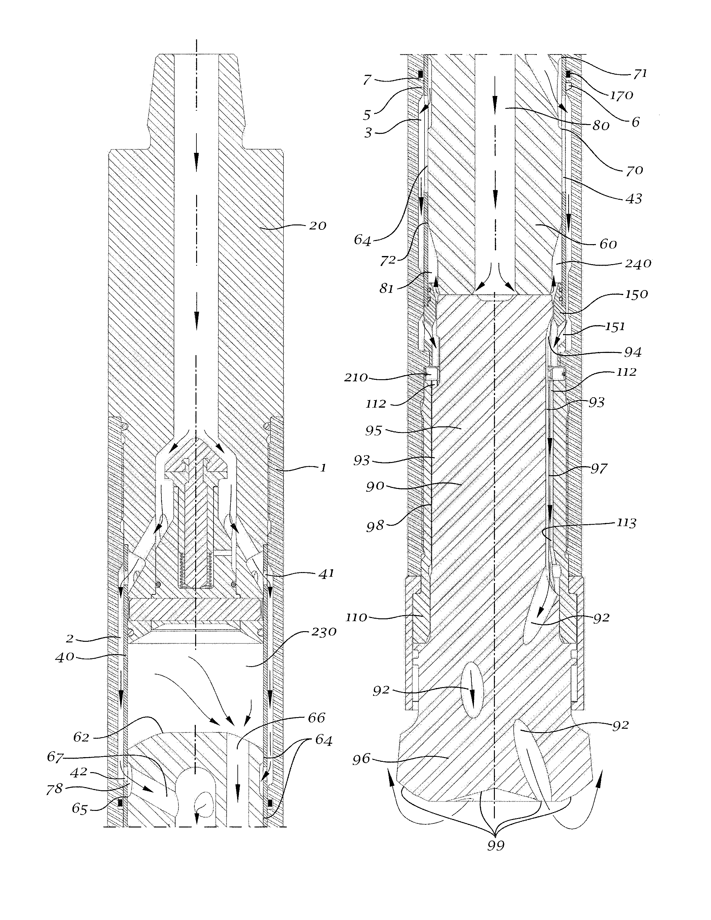
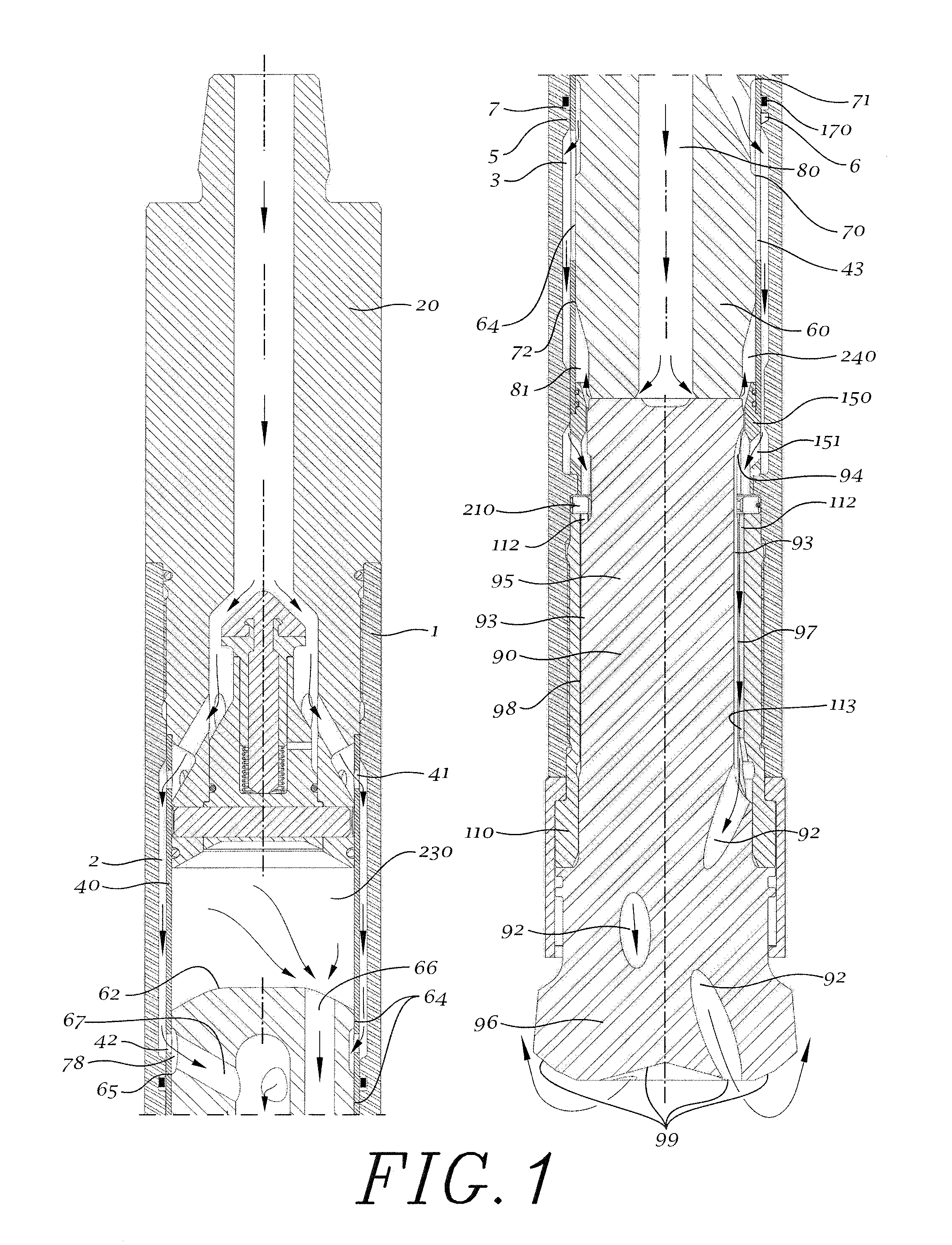
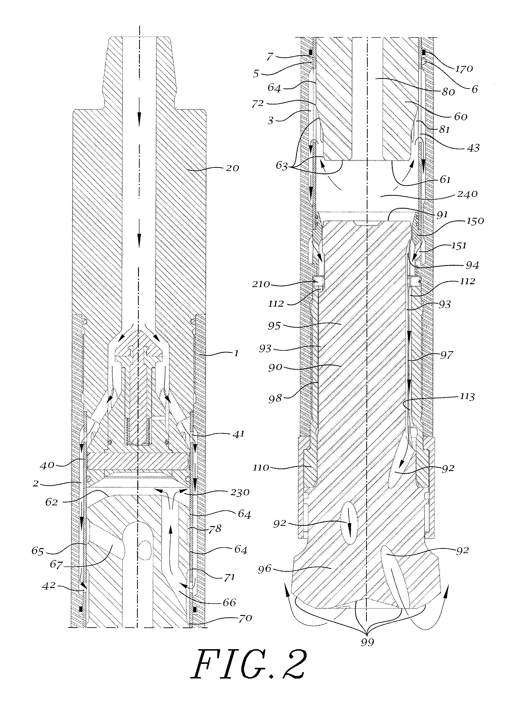
This phenomenon negatively affects the drilling process.
1) Production, where a kind of hammer known as “normal circulation hammer” is used, wherein the rock cuttings produced during the drilling operation are flushed to the ground surface through the annular space defined by the wall of the hole and the outer surface of the hammer and the
drill string, producing wear on the outer surfaces of the hammer and the
drill string by the action of said cuttings. The pressurized fluid coming from the chambers and from the assisted flushing
system is discharged through a central passage inside the
drill bit which extends from its rear end to its front end. This passage may be divided into two or more passages ending in the front face of the
drill bit in such a way that the
discharge of the pressurized fluid is mainly generated from the center and across the front face of the
drill bit towards the
peripheral region of the same and towards the wall of the hole, and then towards the ground surface along the annular space between the hammer and the wall of the hole and between the drill string and the wall of the hole. The rock cuttings are exhausted by drag and are suspended in the pressurized fluid discharged to the bottom of the hole.
In general the soil or rock removed is not used as it is not of interest and suffers from
contamination on its path to the surface.
The pressurized fluid flow with suspended rock cuttings produce wear on the inner surfaces of all the elements that form said central passage.
1)
rate of penetration, which is given by the power generated in the pressurized fluid cycle in the hammer and which value depends on two variables: the pressurized fluid consumption and the cycle's
energy conversion efficiency, this being defined as the power generated per unit of pressurized fluid
mass consumed;
2) durability of the hammer related to wear induced by the pressurized fluid flow dragging rock cuttings toward the ground surface, the durability being strongly dependent on the characteristics of the rock cuttings and the thickness of the parts in contact with the pressurized fluid flow;
3) consumption of pressurized fluid, which is strongly dependent on the passive volume of the front chamber, the passive volume of the rear chamber and the design of the pressurized fluid cycle of the hammer;
4)
deep drilling capacity, which depends on the ability of the hammer to deliver pressurized fluid with a high level of energy to the bottom of the hole;
5) manufacturing costs, which depend on manufacturing complexity, the amount of components of the hammer and the amount of
raw material used;
6) reliability of the hammer, which depends on the quality of the manufacture process and the sturdiness of the design of the tool; and
7) rock cuttings
recovery efficiency (only for reverse circulation hammers), which is mainly related with the capacity of the hammer to seal the hole and prevent the leakage of pressurized fluid and rock cuttings to the annular space formed between the hammer and the wall of the hole and between the drill string and the wall of the hole.
It should be noted that the
rate of penetration, durability of the hammer, pressurized fluid consumption, reliability of the hammer and
deep drilling capacity are factors that have direct incidence in the operational cost for the user.
Therefore, on each cycle the net work exerted by this region on the piston is null, i.e. it does not contribute with the
energy transfer process to the piston, resulting in a reduced rear thrust area.
Moreover, the alignment of the cylinder is a frequent problem in this type of design, which if is notaddressed, induces dissipative forces that drain power from the hammer's cycle.
The presence of bores across the piston weakens the
impact strength of this part of the hammer and implies a more complex manufacturing process.
In addition, the creation of the supply chamber inside the feed tube produces a
delay in the
initiation of the flow when the supply of pressurized fluid to the chambers is enabled, due to the distance between the former and the latter.
The bores also cause an increment in the passive volumes of the chambers, being the main consequence of this a rise in the consumption of pressurized fluid and a reduction in the energy efficiency conversion in the
thermodynamic cycle.
Moreover, the provision of a feed tube requires the use of a piston having a central bore extending along its entire length, resulting in the effects on power already mentioned for the Type A system.
The main disadvantages of this design is the addition of passive volume due to the presence of the second and third sets of passages and the fact that these passages significantly reduce the useful life of the outer casing which is largely dependent on the thickness of its wall.
Also, the provision of an air guide and footvalve requires the use of a piston having a central bore extending along its entire length, resulting in the effects on power already mentioned for the Type A system.
Moreover, the need to discharge the rear chamber requires the use of a piston with a central bore that emerges on the front face of the same, thus reducing even more the rear thrust area and the front thrust area of the piston, which results in a cycle of even less power.
Further, in U.S. Pat. No. 5,113,950 the presence of recesses and bores through the piston weaken the
impact strength of this component.
The disadvantages of this flow system are the same ones as those associated with the Type A and Type D flow systems and, in particular,
impact negatively the design of the drill bit in two aspects.
The first one is the need for a multiplicity of manufacturing processes for producing the channels in the outer surface of the drill bit, which increases the manufacturing cost of the hammer.
The second is that, due to the presence of these channels, the drag surface of the splines, which depend on the contact area of each spline individually and the total number of splines, can in some applications be insufficient.
This last problem can be counterbalanced by lengthening the drill bit, but this implies increasing the cost of the hammer.
The disadvantages in this case (U.S. Pat. No. 4,819,746) are the same as those of the Type A flow system and the design of the drill bit is also negatively impacted in the same two aspects already mentioned for the Type 1 flow system plus a third aspect.


