
Masonry wall panel for retaining bricks

a technology for retaining bricks and masonry walls, applied in the field of masonry works and installations, can solve the problems of cumbersome transportation to the job site, prefabricated panels or liners often do not provide the architecturally satisfactory appearance of real bricks or stones, and long process time-consuming, and achieves rapid and easy insertion of bricks, preventing them from breaking, and increasing the flexural capacity of tabs

Active Publication Date: 2014-01-14
OLDCASTLE BUILDING PROD CANADA INC
View PDF70 Cites 26 Cited by
  • Summary
  • Abstract
  • Description
  • Claims
  • Application Information

AI Technical Summary

Benefits of technology

The patent text describes a design for a panel used in building construction. The design includes channels that are created by ribs on the panel. The depth of the channels is determined by the thickness of the ribs. The panel also has tabs that run along the entire thickness of the ribs and have a v-shaped cross-section. The tabs are designed to have a groove at the bottom of the channels, which increases their flexural capacity and prevents them from breaking when a brick is inserted. This design makes it easy to insert bricks into the panel and allows for bricks that vary in size.

Problems solved by technology

This is a very long process which is time consuming.
These pre-fabricated panels or liners often do not provide an architecturally satisfactory appearance of real brick or stone.
Also, they are often very heavy and are thus difficult and cumbersome to transport to the job site and to install on the building structure.
Another drawback with many of these pre-fabricated panels is that once installed side by side on a surface, the separation line between the panels is clearly visible which makes those prefabricated panels less attractive for someone researching the appearance of a real natural stonework.
A conventional standard brick available on the market would not be suitable with this system.
While this solution can be used with conventional clay bricks, it has the disadvantage of introducing extra steps during the installation of the units, and of requiring extra curing time in order to allow the adhesive to dry.

Method used


Image

  • Masonry wall panel for retaining bricks
  • Masonry wall panel for retaining bricks
  • Masonry wall panel for retaining bricks

Examples


Embodiment Construction

[0058]In the following description, similar features in the drawings have been given similar reference numerals. In order to preserve clarity, certain elements may not be identified in some figures, if they are already identified in a previous figure.

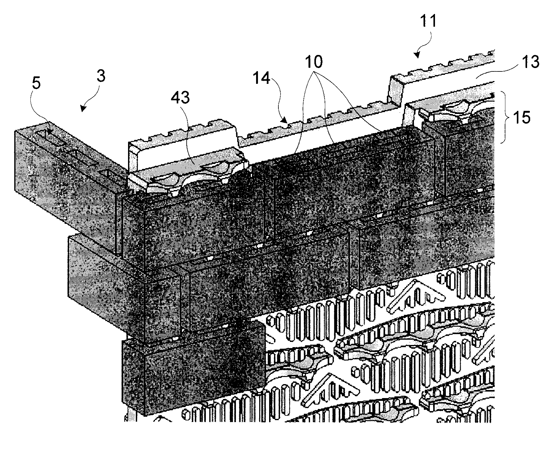
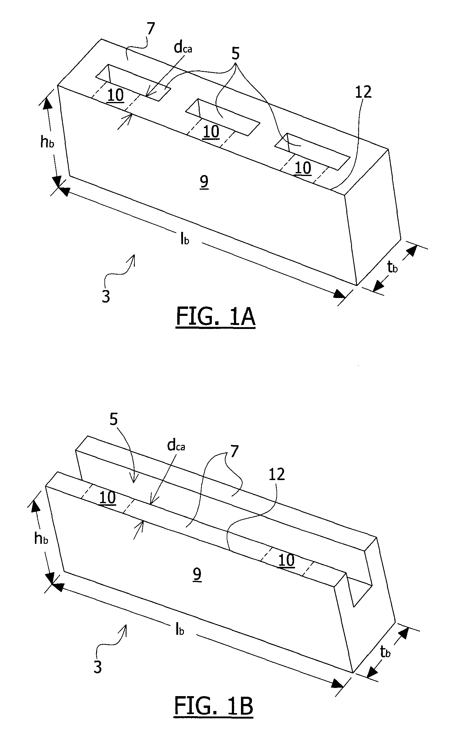
[0059]Referring to FIGS. 1A to 1F, six types of bricks 3 are shown, such as the ones that can be used in combination with a panel of the invention, described further in detail in the following paragraphs. Throughout the description, the term “brick” is not limited to designate conventional clay bricks but refers to any masonry unit made of any material, having various sizes.

[0060]The bricks 3 have an upper side 7, a rear side 9 and a rear top edge 12 intersecting the upper side and the rear side, these upper and rear sides 7, 9 being in reference to the orientation of the bricks 3 when they are inserted in a wall panel of the invention. Once inserted, the upper side 7 of a brick 3 faces upwards relative to the ground and its rear side 9...


PUM


Abstract

The present invention concerns a masonry wall panel assembly comprising a panel and a plurality of bricks. The panel is provided with a plurality of horizontally extending contiguous channels bounded by upper and lower protruding ribs, for fitting a row of bricks. Each channel is also fitted with a plurality of compressible retaining tabs positioned along the upper rib of each channel for retaining bricks inserted therein. The bricks are provided with at least one cavity and at least one compression area so that when a brick is inserted into a channel of the panel, the brick is positioned between the ribs such that the cavity of the brick faces one or more of the tabs located on the channel so that the tabs protrude into the cavity of the brick while at the same time compressing the compression area, thereby retaining the brick within the channel.

Description

CROSS REFERENCE TO RELATED APPLICATIONS[0001]This application is the U.S. national phase of International Application No. PCT / CA2010 / 000133 filed on Jan. 29, 2010 and published in English on Aug. 5, 2010 as International Publication No. WO 2010 / 085894 A1, which application claims priority to U.S. Provisional Application No. 61 / 222,980 filed on Jul. 3, 2009 and also claims priority to International Application No. PCT / CA2009 / 000118 filed on Jan. 30, 2009, the contents of all of which are incorporated herein by reference.FIELD OF THE INVENTION[0002]The present invention relates to the field of masonry works and installations. More particularly, it concerns panels having horizontal channels adapted to receive bricks so as to form a masonry wall.BACKGROUND[0003]Stone masonry and brick masonry facings have been traditionally constructed by skilled workers from individual units, such as bricks, stones, or rocks, set and mortared one after the other into the shape of a wall. This is a very...

Claims


Application Information

Patent Timeline
Patent Type & Authority Patents(United States)
IPC IPC(8): E04F13/08
CPCE04F13/0862E04C2/041E04G21/1883
Inventor BOUCHARD, MICHELPENTERMAN, JOHN
Owner OLDCASTLE BUILDING PROD CANADA INC
Learn More