Parking brake control device

a brake control and brake technology, applied in the direction of anti-theft devices, process and machine control, braking components, etc., can solve the problem of inability to perform the releasing control with good precision, and achieve the effect of preventing clearan

Active Publication Date: 2014-01-07
ADVICS CO LTD
View PDF12 Cites 7 Cited by
  • Summary
  • Abstract
  • Description
  • Claims
  • Application Information

AI Technical Summary

Benefits of technology

[0013]It is therefore possible to ensure the clearance between the friction-applying member and the friction-applied member. The ensuring of the more precise clearance between the friction-applying member and the friction-applied member makes it possible for the parking brake control device to perform the releasing control with good precision.
[0022]If the additional time by which the releasing operation time is extended is thus set based on the maximum wheel cylinder pressure value, the additional time can be set even in a case where the driver pumps the brake pedal. It is therefore possible to prevent the clearance between the friction-applying member and the friction-applied member from being insufficient and to prevent the driver from being given the feeling that the brake is dragging.

Problems solved by technology

Therefore, simply terminating the operation of the motor after the specified period of time has elapsed since the point when the motor current became no greater than the specified value makes it impossible to perform the releasing control with good precision, because the clearance that is provided between the brake pad and the brake disc is not constant.

Method used


Image

  • Parking brake control device
  • Parking brake control device
  • Parking brake control device

Examples


first embodiment

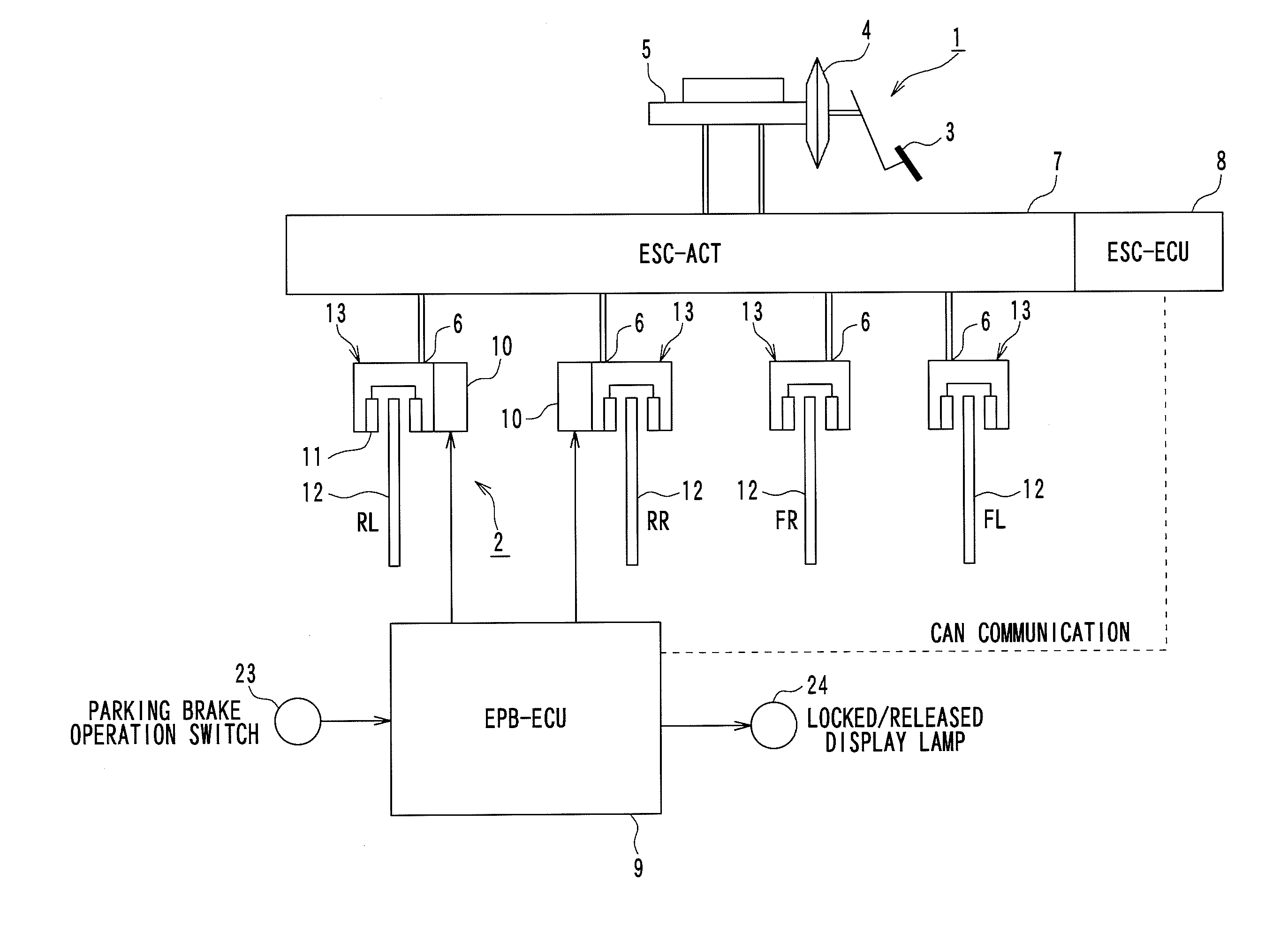
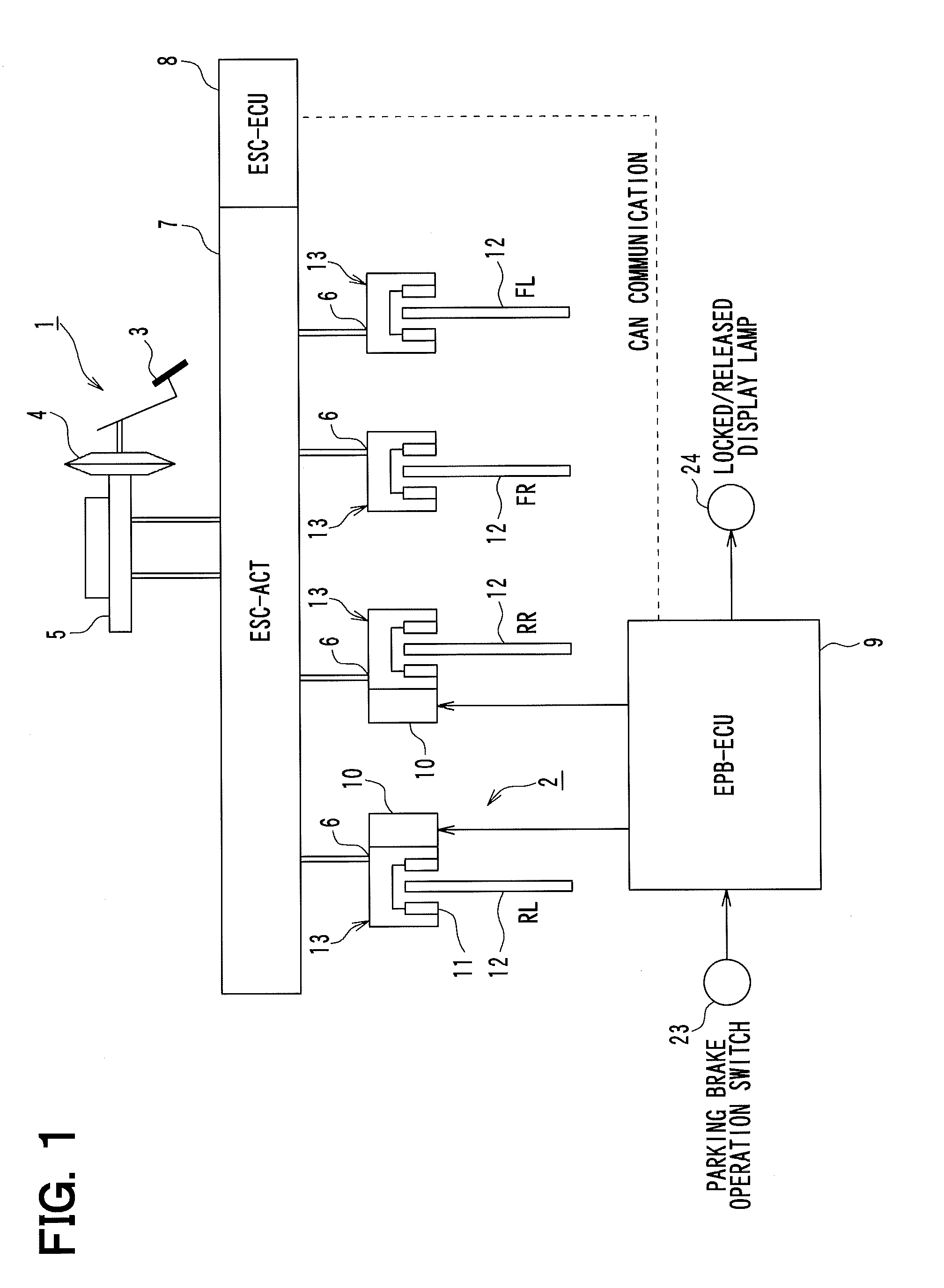
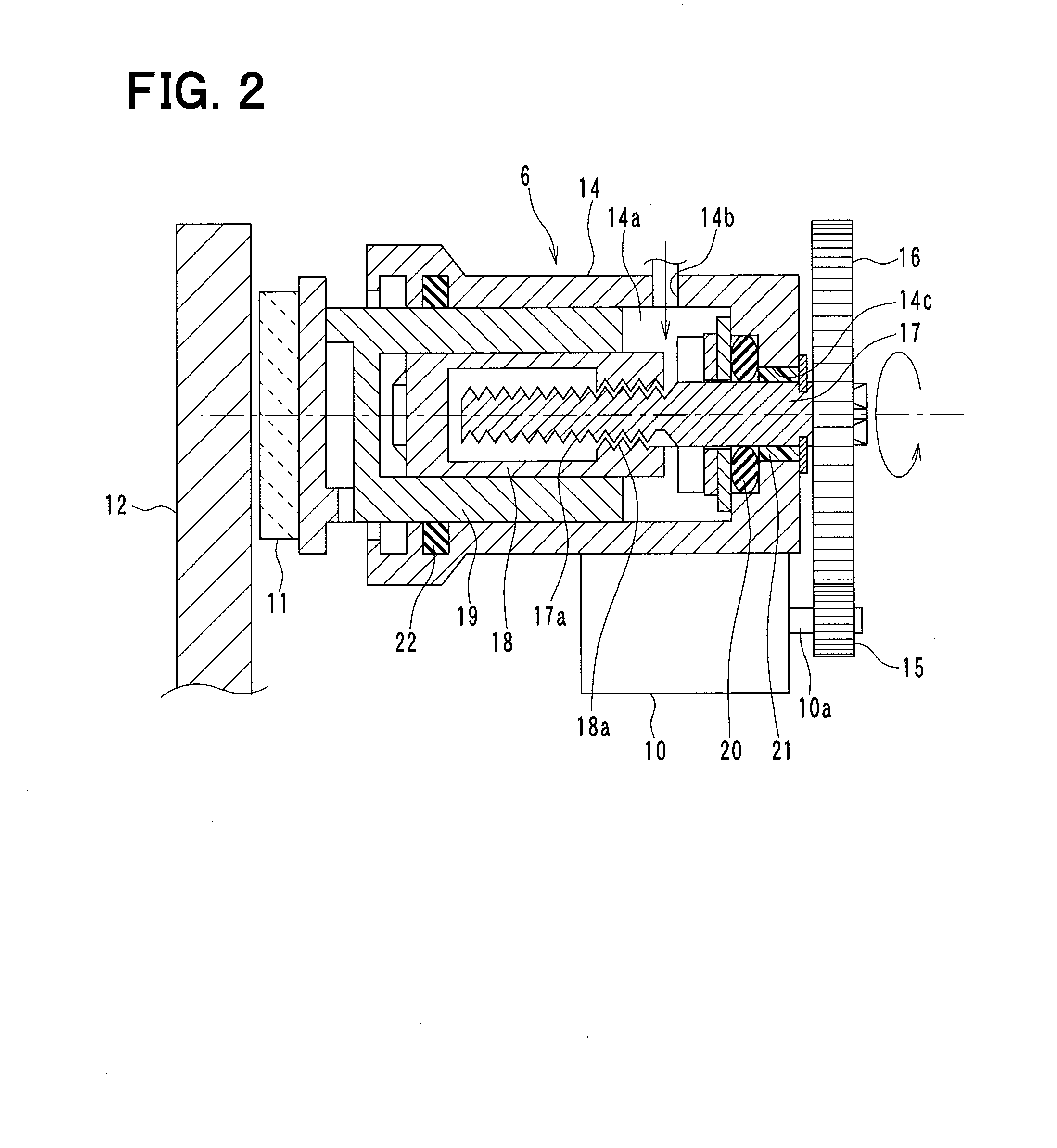
[0035]A first embodiment of the present invention will be explained. The present embodiment uses as an example a vehicle brake system in which a disc brake type EPB is applied to a rear wheel. FIG. 1 is a schematic figure that shows an overall configuration of the vehicle brake system to which a parking brake control device according to the present embodiment is applied. FIG. 2 is a schematic section view of a rear wheel brake mechanism that is provided in the brake system. The present embodiment will be explained with reference to these drawings.

[0036]As shown in FIG. 1, the brake system is provided with a service brake 1 that generates a braking force based on a pedal force of a driver and with an EPB 2 for restricting the movement of the vehicle when it is parked.

[0037]For the service brake 1, the pedal force, which corresponds to the extent to which the driver depresses a brake pedal 3, is multiplied by a servo unit 4. A brake fluid pressure that corresponds to the multiplied pe...

second embodiment

[0082]A second embodiment of the present invention will be explained. In the present embodiment, the configuration of the brake system and the method of the releasing control processing are modified from what they were in the first embodiment, but the present embodiment is otherwise the same as the first embodiment, so only the portions that are different from the first embodiment will be explained.

[0083]In a case where the braking force is generated only by the EPB 2, it is acceptable to take into consideration the braking force of only the EPB 2, as in the first embodiment, but in a case where the braking force is generated by the driver's depressing of the brake pedal 3, it is preferable for the effect of the driver's depressing of the brake pedal 3 to be taken into account in the performing of the releasing control. Accordingly, in the present embodiment, the releasing control that is performed is also compatible with a case in which the driver is depressing the brake pedal 3.

[0...


PUM


Abstract

A parking brake control device performs a releasing control with good precision by more precisely maintaining clearance between a friction-applying member and a friction-applied member. During a releasing control, a timing at which a braking force generated by an electric parking brake 2 drops to zero is detected based on a change in a motor current, and a second releasing operation time is set according to the magnitude of the motor current at the time the braking force drops to zero. This makes it possible for the second releasing operation time to be set in accordance with fluctuations in a motor load due to temperature changes or the like. Therefore, a clearance between a brake pad and a brake disc can be kept constant according to the motor load.

Description

TECHNICAL FIELD[0001]The present invention relates to a parking brake control device that performs locking and releasing control of an electric parking brake (hereinafter called the EPB).BACKGROUND ART[0002]The use of a parking brake to restrict the movement of a vehicle when it is parked is known. The parking brake may be, for example, a manual type in which an operating force is transmitted to a brake mechanism by the pulling of a brake cable by a operating lever, an electric type in which the rotational force of a motor is transmitted to the brake mechanism, or the like.[0003]With the electric type parking brake, or EPB, to lock the EPB, the motor rotates in a locking direction (rotates in a forward direction), and the rotational force of the motor is transmitted to the brake mechanism, generating a braking force. In that state, the operation of the motor is stopped. To release the EPB, the motor rotates in a releasing direction (rotates in reverse), which cancels the braking for...

Claims


Application Information

Patent Timeline
Patent Type & Authority Patents(United States)
IPC IPC(8): F16D65/18F16D55/22
CPCF16D2125/40F16D2121/24F16D2125/48F16D2065/386F16D2123/00F16D2121/02F16D65/18B60T7/042B60T13/741B60T7/107B60T8/32
Inventor WATANABE, TAKASHITSUZUKI, TETSUAKIKONDO, KAZUMAYUASA, KENTARO
Owner ADVICS CO LTD
Why Eureka
Try Eureka