
Variable valve system control apparatus

a control apparatus and valve technology, applied in the direction of braking systems, process and machine control, instruments, etc., can solve the problems of reducing the control range of valve timing and operation angle, affecting the operation of the valve, so as to achieve a wide control range of the operation angle and keep the upper guard allowance small

Inactive Publication Date: 2013-12-31
TOYOTA JIDOSHA KK
View PDF17 Cites 0 Cited by
  • Summary
  • Abstract
  • Description
  • Claims
  • Application Information

AI Technical Summary

Benefits of technology

[0012]The invention therefore provides a control apparatus of a variable valve system capable of ensuring a relatively wide operation angle control range while also being able to reliably avoid valve stamp.
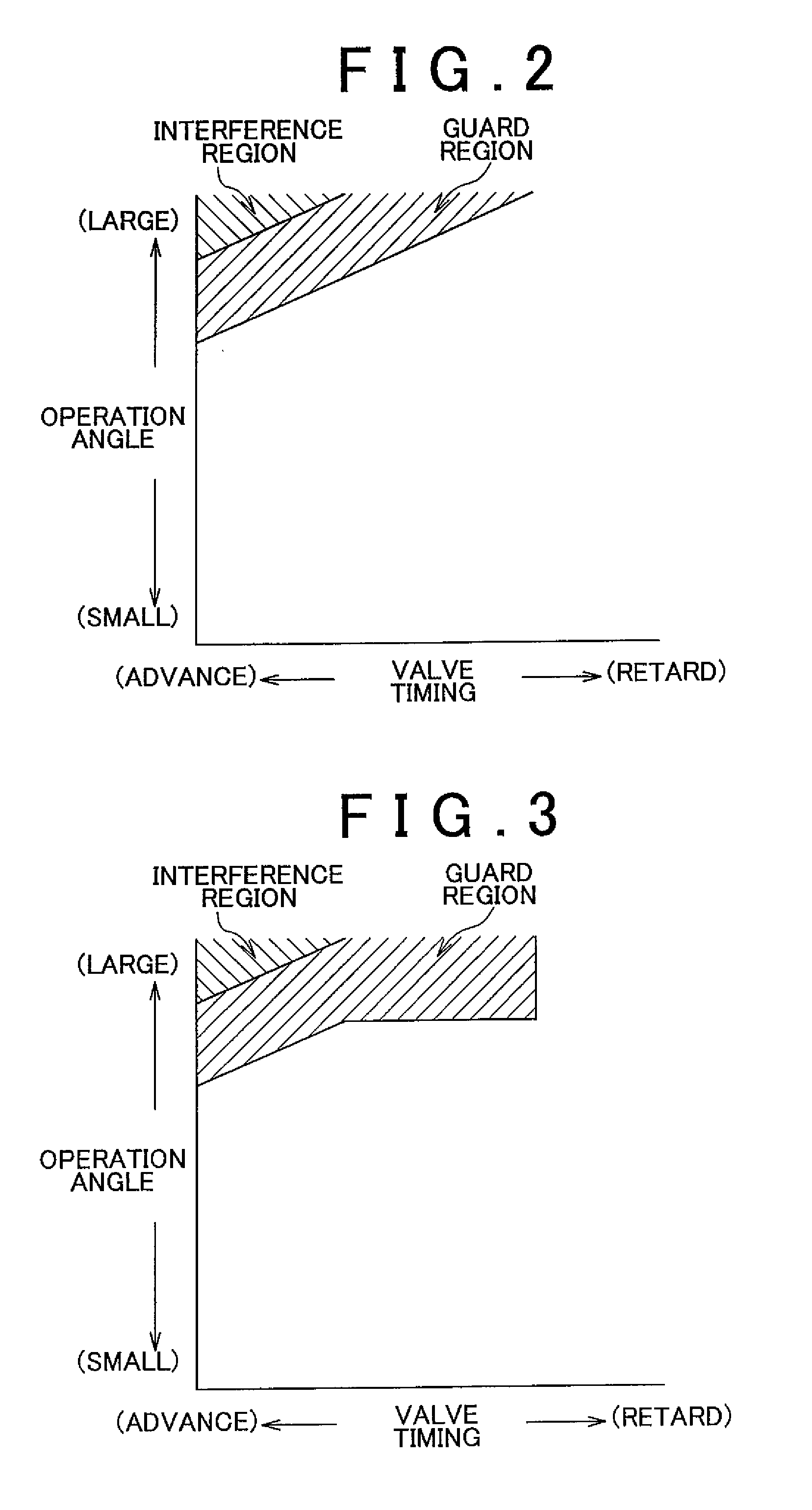
[0014]Thus, a first aspect of the invention relates to a control apparatus of a variable valve system. This control apparatus includes a variable valve timing mechanism that performs variable control of the valve timing of an intake valve of an internal combustion engine, a variable operation angle mechanism that performs variable control of the operation angle of the intake valve, and a control unit that performs drive control of the variable valve timing mechanism and the variable operation angle mechanism. The control unit sets an upper guard for the operation angle according to an actual value of the valve timing, and when a target value of the valve timing is a value on the retard side of a specified determining value, the control unit reinforces the upper guard compared with when the target value of the valve timing is not a value on the retard side of the specified determining value. With this control apparatus, the upper guard for the operation angle is reinforced, i.e., the upper guard is set farther away from (i.e., with a larger allowance with respect to) the boundary between the interference region and the non-interference region, only when the target value of the valve timing of the intake valve is set to a value on the retard side and it is highly likely that valve stamp will occur. On the other hand, under normal circumstances in which the target value of the valve timing of the intake valve is not set to a value on the retard side and it is not highly likely that valve stamp will occur, the upper guard is set closer to the boundary between the interference region and the non-interference region, i.e., the upper guard allowance is kept small. Therefore, according to this structure, a relatively wide operation angle control range can be ensured while valve stamp is also able to be reliably avoided.
[0016]A second aspect of the invention relates to a control apparatus of a variable valve system. This control apparatus includes a variable valve timing mechanism that performs variable control of the valve timing of an exhaust valve of an internal combustion engine, a variable operation angle mechanism that performs variable control of the operation angle of the exhaust valve, and a control unit that performs drive control of the variable valve timing mechanism and the variable operation angle mechanism. The control unit sets an upper guard for the operation angle according to an actual value of the valve timing, and when a target value of the valve timing is a value on the advance side of a specified determining value, the control unit reinforces the upper guard compared with when the target value of the valve timing is not a value on the advance side of the specified determining value. With this structure, the upper guard for the operation angle is reinforced, i.e., the upper guard is set farther away from (i.e., with a larger allowance with respect to) the boundary between the interference region and the non-interference region, only when the target value of the valve timing of the exhaust valve is set to a value on the advance side and it is highly likely that valve stamp will occur. On the other hand, under normal circumstances in which the target value of the valve timing of the exhaust valve is not set to a value on the advance side and it is not highly likely that valve stamp will occur, the upper guard is set closer to the boundary between the interference region and the non-interference region, i.e., the upper guard allowance is kept small. Therefore, according to this structure, a relatively wide operation angle control range can be ensured while valve stamp is also able to be reliably avoided.

Problems solved by technology

If the actual value of the valve timing exceeds that target value and overshoots to the advance side in this state, the valve timing and the operation angle may enter an interference region where valve stamp occurs.
However, if the upper guard is given a lot of allowance, the control range of the valve timing and the operation angle will end up being reduced.

Method used


Image

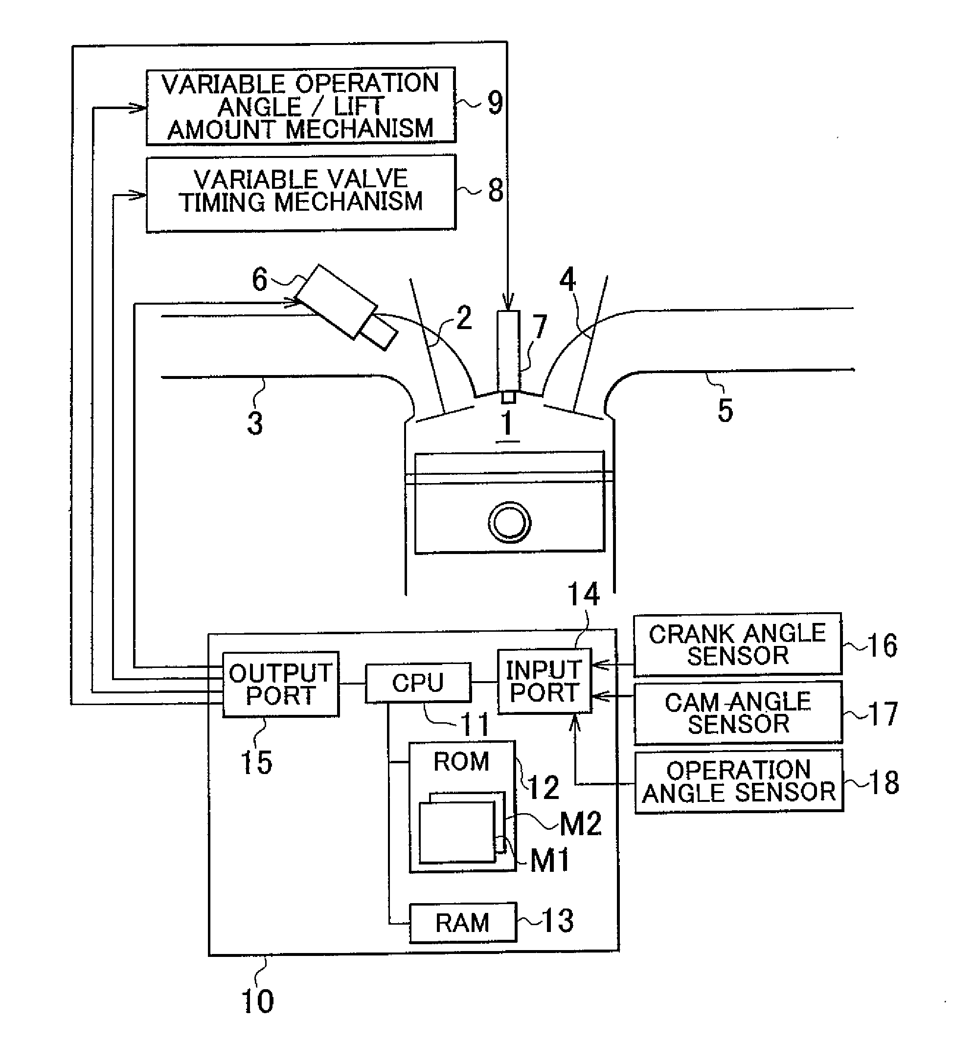
  • Variable valve system control apparatus
  • Variable valve system control apparatus
  • Variable valve system control apparatus

Examples


Embodiment Construction

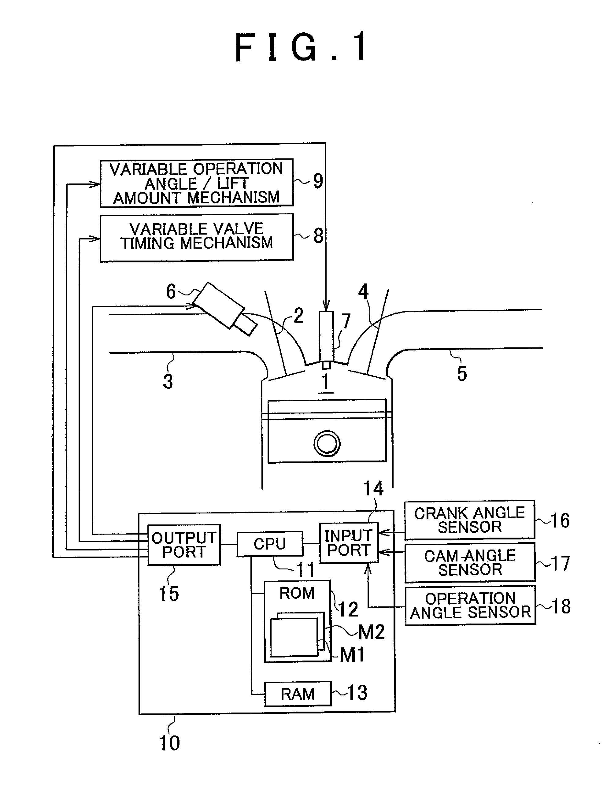
[0025]Hereinafter, a control apparatus of a variable valve system according to a first example embodiment of the invention will be described in detail with reference to FIGS. 1 to 4.

[0026]FIG. 1 is a view of the structure of an internal combustion engine, and the control system thereof, to which the control apparatus of a variable valve system according to a first example embodiment of the invention may be applied. A combustion chamber 1 of the internal combustion engine to which this example embodiment is applied is connected to an intake pipe 3 via an intake valve 2, and connected to an exhaust pipe 5 via an exhaust valve 4. The intake pipe 3 is provided with an injector 6 that injects fuel into intake air that flows through the intake pipe 3. Also, the combustion chamber 1 is provided with a spark plug 7 that ignites the mixture of air and fuel introduced into the combustion chamber 1.

[0027]A valve system of the intake valve 2 of this internal combustion engine is provided with a...


PUM


Abstract

A control apparatus of a variable valve system includes a variable valve timing mechanism that performs variable control of the valve timing of an intake valve of an internal combustion engine, a variable operation angle mechanism that performs variable control of the operation angle of the intake valve, and a control unit that performs drive control of the variable valve timing mechanism and the variable operation angle mechanism. The control unit sets an upper guard for the operation angle according to an actual value of the valve timing, and when a target value of the valve timing is a value on the retard side of a specified determining value, the control unit reinforces the upper guard compared with when the target value of the valve timing is not a value on the retard side of the specified determining value.

Description

INCORPORATION BY REFERENCE[0001]The disclosure of Japanese Patent Application No. 2010-025284 filed on Feb. 8, 2010 including the specification, drawings and abstract is incorporated herein by reference in its entirety.BACKGROUND OF THE INVENTION[0002]1. Field of the Invention[0003]The invention relates to a control apparatus of a variable valve system that performs variable control of valve timing of intake and exhaust valves in an internal combustion engine, and variable control of the operation angle of those valves.[0004]2. Description of the Related Art[0005]In recent years, variable valve systems that vary the valve characteristics of intake and exhaust valves have been put into practical use as systems applied to internal combustion engines mounted in vehicles and the like. In internal combustion engines that employ such variable valve systems, performance with regard to engine output, fuel efficiency, and emissions and the like is improved by appropriately adjusting the valv...

Claims


Application Information

Patent Timeline
Patent Type & Authority Patents(United States)
IPC IPC(8): G06F17/00
CPCF02D13/0215F02D13/0226Y02T10/18Y02T10/12
Inventor HAYASHI, KOTAITO, TOKIJITAKIMOTO, FUMITO
Owner TOYOTA JIDOSHA KK
Learn More