
Tube tool device

a technology of tool or implement, which is applied in the field of new and improved tool or implement holders, can solve the problems of mugs that can chip the bathtub or shower tile, and many razor blades that cannot be received or a proprietary head

Inactive Publication Date: 2013-12-17
HANDSFREE MARKETING
View PDF29 Cites 14 Cited by
  • Summary
  • Abstract
  • Description
  • Claims
  • Application Information

AI Technical Summary

Problems solved by technology

Although there are razor blades that can be received on a universal head, many razor blades can only be received or a proprietary head.
The bath and shower are not convenient for the use of cake soap shaving lather with a mug and brush.
If the mug is dropped, it can break, since they are normally made of ceramic material.
In addition, the mug can chip the bathtub or shower tile.
The aerosol can has a disadvantage in that, if it is kept in the shower or around the tub, it gets wet and the metal of the aerosol rust causing rust stains in the tile grout and the like.
One of the problems that is encountered by people when traveling is the amount of space required for their shaving gear including the razor blade with its frame and the shaving lather source, whether it is soap cake shaving lather applied with a brush or shaving lather applied from a flexible tube or shaving lather applied from an aerosol can.
Another problem is that when people shave around the bathtub or shower, the separate components, the razor blade with handle and the source of the shaving cream, take up space which is normally in a premium around a bathtub or in a shower stall.
Many compositions such as shaving cream, cleaning preparations, and the like, are thick or gelatinous materials that cannot easily be removed from a rigid bottle.
The tube and tool or implement frequently get separated, and thus when the user wants to use the composition, they cannot find the implement or tool or vice versa.
In addition, because of the relatively low cost for many compositions, tools are made cheaply and skimpily and do not have and adequate handle.

Method used


Image

  • Tube tool device
  • Tube tool device
  • Tube tool device

Examples


Embodiment Construction

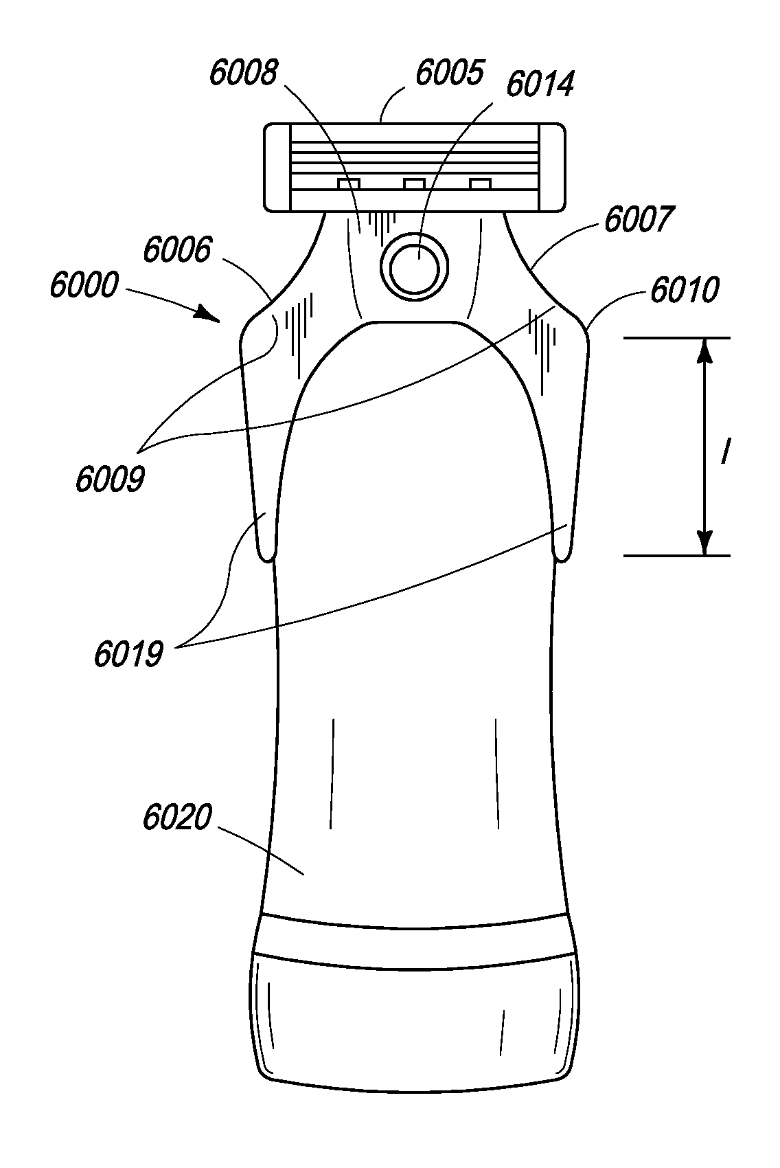
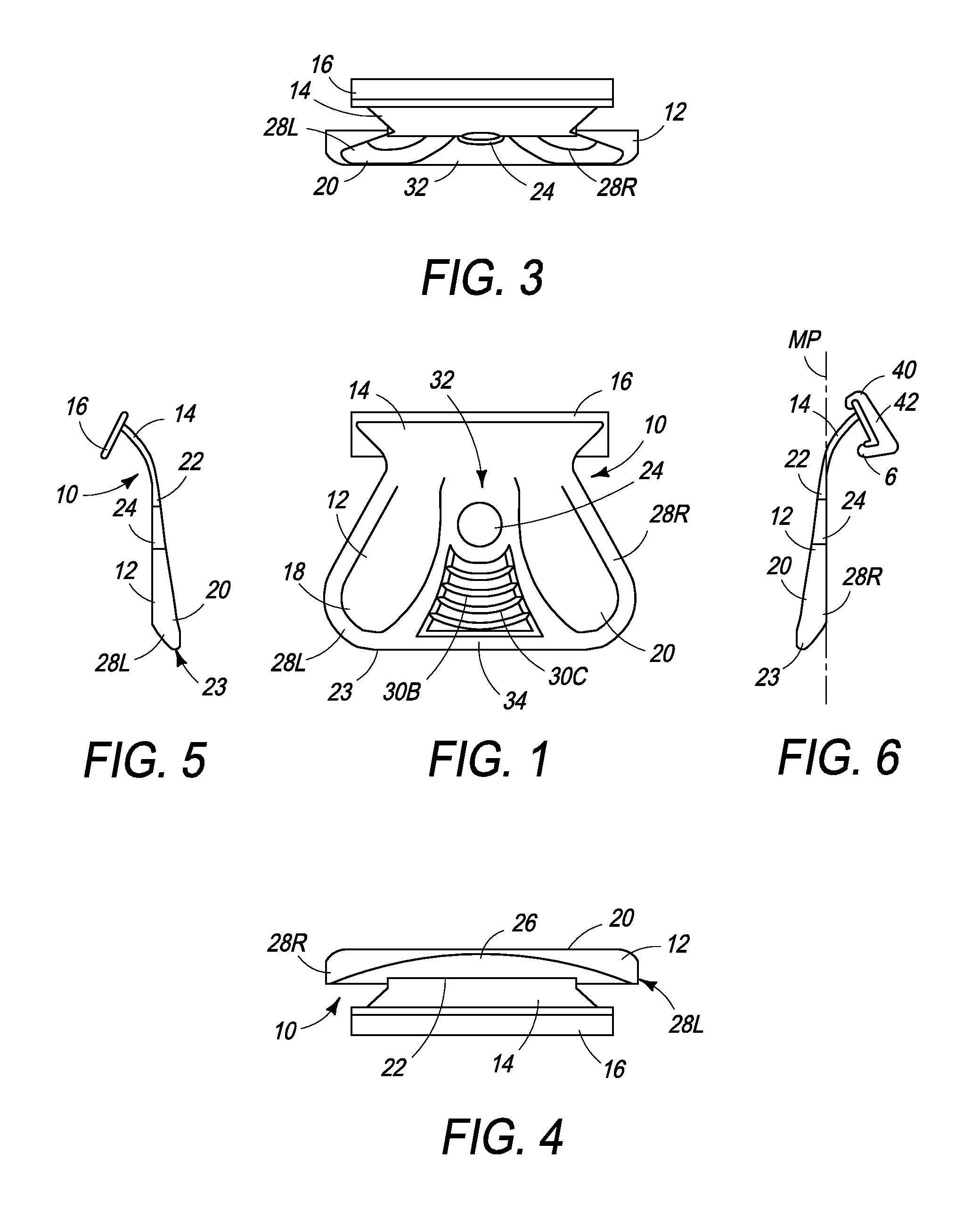
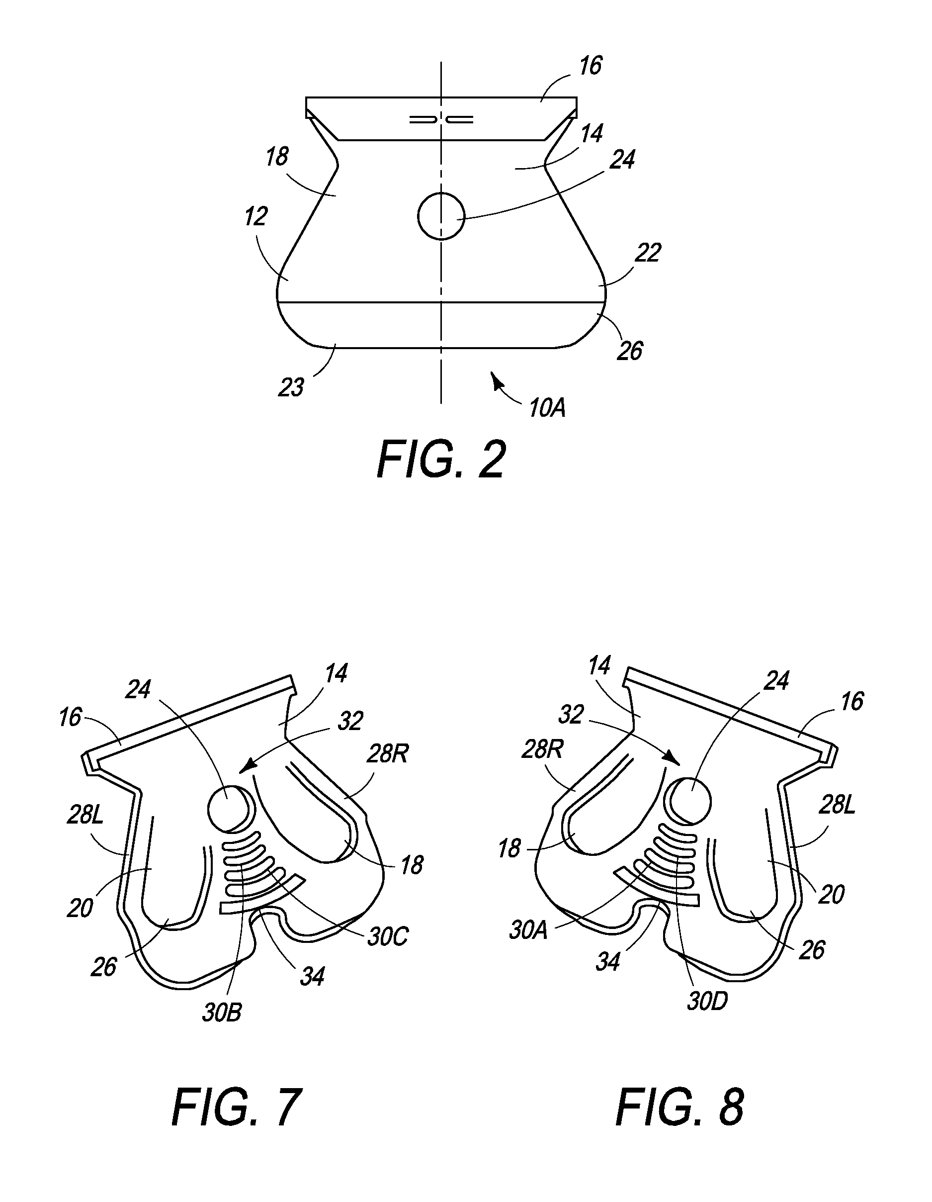
[0105]Referring to FIGS. 1-8, the razor blade attachment unit 10 comprises a frame 12 having an arm 14 extending upwardly and outwardly there from and a razor blade attachment plate 16 secured to the end of the arm 14. Alternatively, a proprietary razor blade attachment assembly can be used (not shown). The razor blade attachment plate 16 can be a universal attachment plate which will receive most razor blades manufactured today. However, some razor blades cannot be secured by the universal attachment plate and the proprietary attachment assembly must be used for the attachment of such blades if they are to be used.

[0106]The frame 12 has a ribbed front side 20 and a planar back side 22. A hole 24 extends through the frame from the ribbed front side to the planar back side adapted to receive a hanger to support the razor or a fastener, such as a rivet, to secure the frame to the sealed end or flexible tube. The ribbed front side 20 has a pair of U-shaped ribs 28R and 28L on the right...


PUM

PropertyMeasurementUnit
angleaaaaaaaaaa
angleaaaaaaaaaa
diameteraaaaaaaaaa

Abstract

The present invention is directed to an implement holder and a flexible tube handle that has semi-rigid or flexible walls. The tube handle has a frame adapted to be removably secured to the sealed end of the flexible tube. The frame has an attachment portion and a tool portion. The attachment portion has a first surface adapted to generally encircle and / or grip a portion of the sealed end or body of the flexible tube and the tool portion has a tube holder adapted to receive a tool or having a tool affixed thereto.

Description

CROSS-REFERENCE[0001]This application is a continuation in part of U.S. patent application Ser. No. 11 / 412,054 filed Apr. 26, 2006 now U.S. Pat. No. 8,028,417 and further relies on U.S. Provisional Application No. 61 / 042,355 filed on Apr. 4, 2008 for priority.FIELD OF THE INVENTION[0002]The present invention is directed to a new and improved tool or implement holder, such as for a razor, employing a semi-rigid or flexible tube containing a composition, such as shaving cream, that works in association with the tool or implement, such as a razor blade attachment at the end of the tube which can receive and detachably secure a razor blade. The body of the tube serves as a handle for the tool or implement. Furthermore, in certain embodiments, the tube tool, together with its body, is detachable from the tube.BACKGROUND OF THE INVENTION[0003]There are many implements or tools used today that are used in association with a composition; and there are many compositions in use today that req...

Claims


Application Information

Patent Timeline
Patent Type & Authority Patents(United States)
IPC IPC(8): B65D35/36B65D35/24
CPCB26B21/446B65D35/24B65D35/36B25G1/10A45D40/28
Inventor HOSSEINI, BIJANSTEVENSON, SCOTT HAYNES
Owner HANDSFREE MARKETING
Learn More