Machining apparatus with reduced cutter vibrations

a technology of machining apparatus and cutter, which is applied in the field of manufacturing, can solve the problems of vibration, chatter marks and/or cutter walking, unwanted defects in materials, etc., and achieve the effect of shortening the unsupported length of the tool and reducing the vibration of the tool during the machining operation

Active Publication Date: 2013-12-10
THE BOEING CO
View PDF13 Cites 1 Cited by
  • Summary
  • Abstract
  • Description
  • Claims
  • Application Information

AI Technical Summary

Benefits of technology

[0012]In another advantageous embodiment, a method for reducing vibration in a tool may comprise altering the temperature of a collar to increase an inner diameter of an inner cylinder to be larger than an outer diameter of a cutter, the collar comprising a housing and the inner cylinder in which the inner diameter of the inner cylinder may be smaller than the outer diameter of the cutter, the housing may have a cross section with a shape of a circle. Then, a cutter may be inserted through the inner cylinder of the collar. Next, the cutter and collar may be allowed to cool, thereby creating a clamping force between the cutter and the collar. Next, the collar in which the cutter may be connected to a cutter holder may be positioned in which positioning may be relative to a machining area on a workpiece. Next, a cutter and collar may be rotated. Vibrations in the cutter may be reduced due to the collar shortening the unsupported length of the cutter. Finally, the cutter may be contacted with the workpiece at a machining area in which the workpiece may be made of at least one of titanium, aluminum, and steel, and the collar may reduce vibration of the cutter while rotating with the cutter.
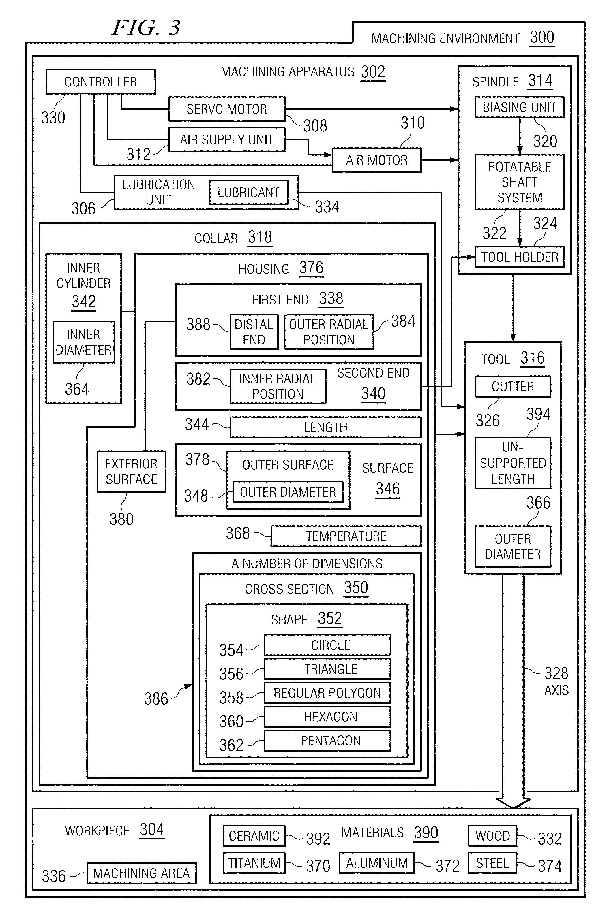
[0013]In one advantageous embodiment, an apparatus may comprise a housing having a first end, a second end, and a number of dimensions in which the number of dimensions of the housing is configured to reduce vibrations of a tool during a machining operation. Also, the apparatus may comprise a inner cylinder extending through the housing from the first end to the second end in which the inner cylinder is configured to receive the tool at the first end and is configured to a engage a tool holder at the second end.
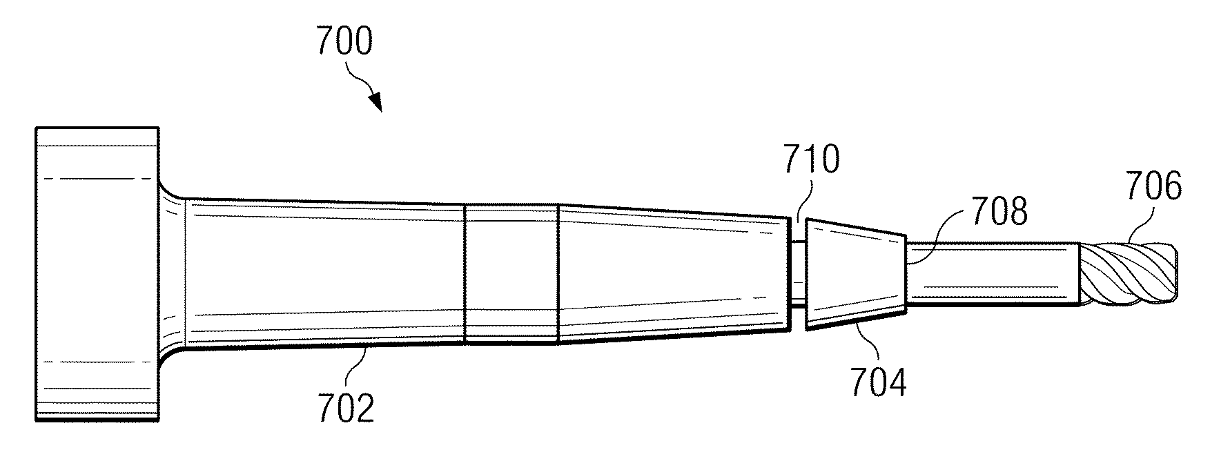
[0014]In another advantageous embodiment, an apparatus may comprise a housing having a first end, a second end, a number of dimensions, a length, an outer diameter, and an exterior surface, the length and the outer diameter of the housing may be selected such that vibration of the tool during a machining operation is reduced by shortening the unsupported length of the tool, and the number of dimensions having a cross section with a shape of a circle. The apparatus may also comprise an inner cylinder, concentric with and extending through the housing from the first end to the second end in which the channel is configured to receive a tool at the first end and is configured to engage a tool holder at the second end in which an inner diameter of the inner cylinder is less than an outer diameter of the tool, and the housing and the inner cylinder forming a collar and further comprising: the tool holder in which the apparatus may be flush against the tool holder and a spindle system connected to the tool holder in which the spindle may be configured to rotate the tool holder. The apparatus may also comprise a machining apparatus in which the spindle system may be located in the machining apparatus. An outer surface extending from the second end to the first end, the second end being an inner radial position adjacent to the tool holder, the outer surface diameter tapering from the second end to the first end, and the first end being an outer radial position coexistent with an exterior surface of the housing on a distal end of the housing for engaging a machining area on a workpiece.

Problems solved by technology

While cutters are in operation they experience vibrations.
Vibrations may cause chatter marks and / or cutter walking.
Cutter walking and chatter marks may cause unwanted defects in the materials and may require manual correction by hand.
Using different length cutters causes a loss in time due to switching out different cutting tool assemblies.
Furthermore, long slender cutting tools for deep recess milling may be expensive and may sometimes be custom made.
These custom made cutters may be even more expensive.

Method used


Image

  • Machining apparatus with reduced cutter vibrations
  • Machining apparatus with reduced cutter vibrations
  • Machining apparatus with reduced cutter vibrations

Examples


Embodiment Construction

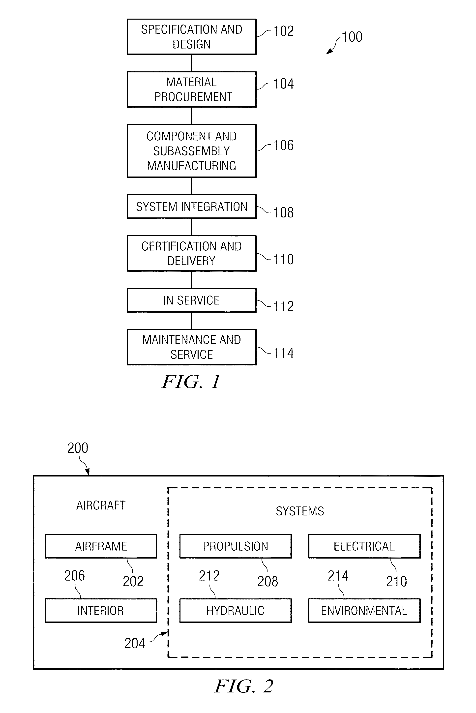
[0026]Referring more particularly to the drawings, embodiments of the disclosure may be described in the context of the aircraft manufacturing and service method 100 as shown in FIG. 1 and aircraft 200 as shown in FIG. 2. Turning first to FIG. 1, a diagram illustrating an aircraft manufacturing and service method is depicted in accordance with an advantageous embodiment. During pre-production, exemplary aircraft manufacturing and service method 100 may include specification and design 102 of aircraft 200 in FIG. 2 and material procurement 104.

[0027]During production, component and subassembly manufacturing 106 and system integration 108 of aircraft 200 in FIG. 2 takes place. Thereafter, aircraft 200 in FIG. 2 may go through certification and delivery 110 in order to be placed in service 112. While in service by a customer, aircraft 200 in FIG. 2 may be scheduled for routine maintenance and service 114, which may include modification, reconfiguration, refurbishment, and other mainten...


PUM

PropertyMeasurementUnit
temperatureaaaaaaaaaa
lengthaaaaaaaaaa
outer diameteraaaaaaaaaa

Abstract

In one advantageous embodiment, an apparatus may comprise a housing having a first end, a second end, and a number of dimensions. Also, the apparatus may comprise a inner cylinder extending through the housing from the first end to the second end in which the inner cylinder is configured to receive a tool at the first end and is configured to a engage a tool holder at the second end in which the number of dimensions of the housing is configured to reduce vibrations during a machining operation.

Description

BACKGROUND INFORMATION[0001]1. Field[0002]The present disclosure relates generally to manufacturing, and in particular, to a method and apparatus for machining and cutting materials. Still more particularly, the present disclosure relates to a method and apparatus for reducing cutter vibration during a machining operation.[0003]2. Background[0004]Manufacturing may involve the use of tools and / or labor to create items for use or sale. In aerospace manufacturing, these items may include, for example, without limitation, aircraft, aircraft parts, missiles, rockets, and / or spacecraft. In manufacturing various items, a number of different operations may be performed. The number of different operations may include, for example, without limitation, milling, machining, extrusion, pressing, rolling, piercing, machining, drilling, routing, cutting, and curing.[0005]With respect to machining, a machine tool may be used with a tool such as a cutting tool to cut a workpiece to a desired geometry...

Claims


Application Information

Patent Timeline
Patent Type & Authority Patents(United States)
IPC IPC(8): B23C3/00
CPCB23B31/005B23C5/003B23Q11/0035B23B2240/28B23B2250/16B23B2260/026Y10T74/2121Y10T408/03Y10T408/76Y10T408/8925Y10T409/303808
Inventor HECK, DAVID P.HANCOCK, RANDOLPH B.
Owner THE BOEING CO
Why Eureka
Try Eureka