
Method and apparatus for measurement of temperature and rate of change of temperature

a technology of temperature and rate of change, applied in the field of measuring temperature, can solve the problems of inability to accurately measure inability to respond fast enough to track the actual temperature of the media, fragile and impractical for sustained use, etc., to eliminate or substantially minimize the disadvantages, accurate measurement of the temperature of the thermocouple, and high fidelity measurement

Inactive Publication Date: 2013-12-10
GARDINER DAVID PHILLIP
View PDF3 Cites 49 Cited by
  • Summary
  • Abstract
  • Description
  • Claims
  • Application Information

AI Technical Summary

Benefits of technology

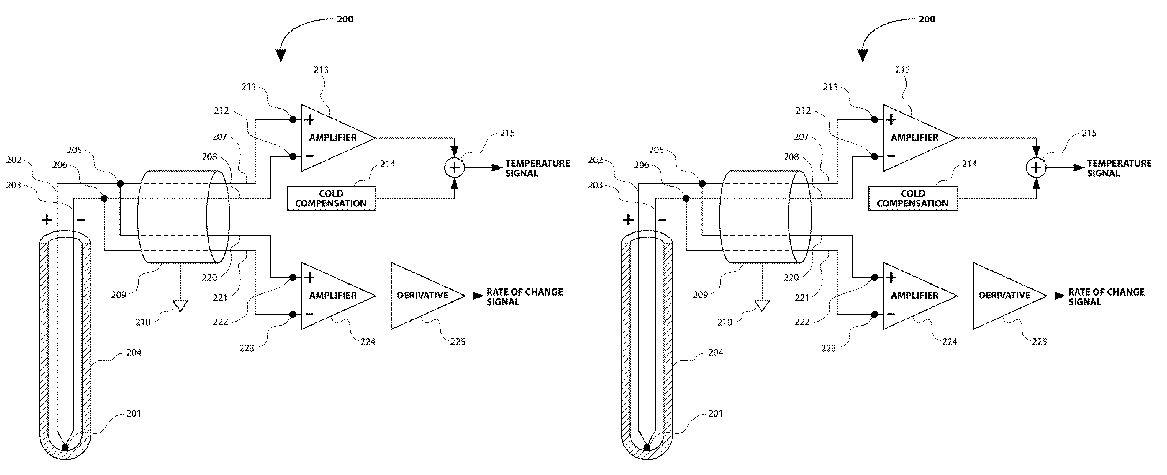
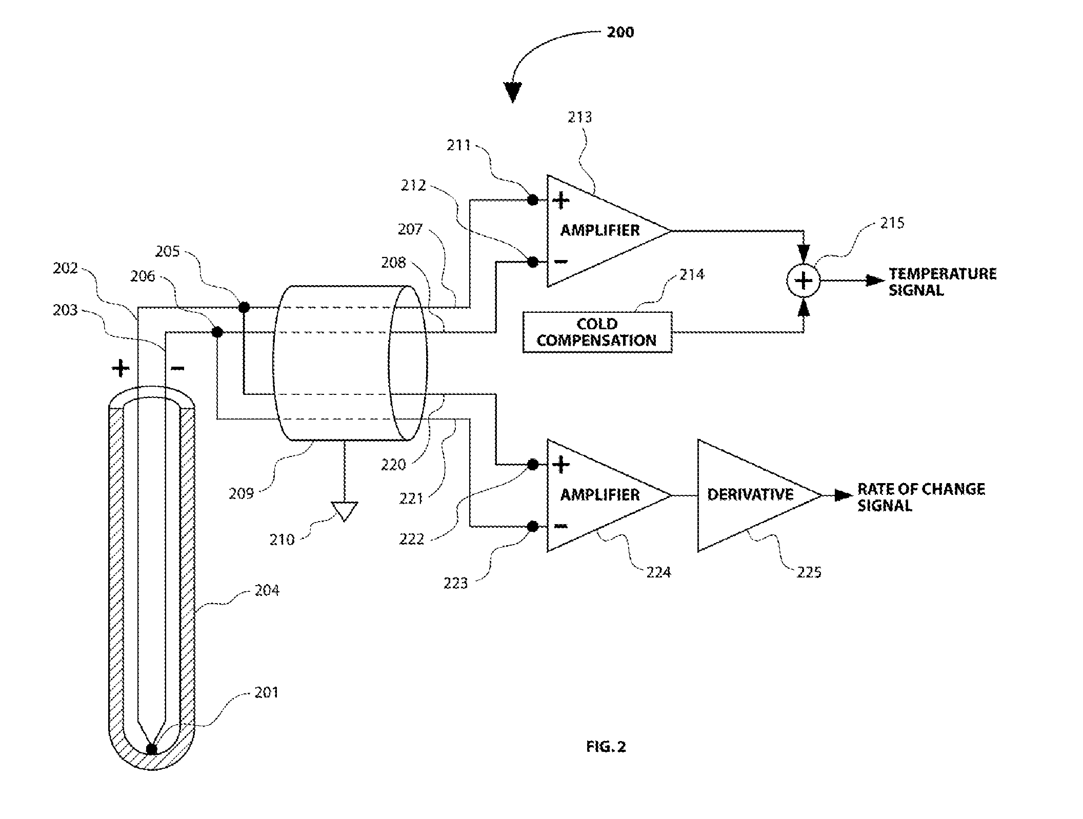
The present invention provides a thermocouple measuring device that can accurately measure the temperature of a thermocouple and its rate of change in a high fidelity manner. This is done by using two sub-circuits, one measuring the temperature of the thermocouple and the other measuring the rate of change in temperature. The first sub-circuit measures the temperature using two different thermocouple alloys, while the second sub-circuit measures the difference in temperature between the measuring junction of the thermocouple and the effective cold junction of the thermocouple using substantially identical material. The two sets of data are then summed to give an accurate measurement of the temperature of the thermocouple's measuring junction. This invention eliminates or minimizes the disadvantages of prior art techniques with respect to signal noise effects on the rate of change in temperature measurement.

Problems solved by technology

This can be difficult or impossible if the temperature of the media changes rapidly.
In many cases involving rapid temperature changes, the thermocouple cannot respond fast enough to track the actual temperature of the media unless the measuring junction is extremely small, and therefore fragile and impractical for sustained use.
Despite being known for over fifty years, the technique of thermocouple time lag compensation has not been widely used.
One reason for this is the difficulty in obtaining a high fidelity derivative signal from a thermocouple.
Thus, the signal is highly vulnerable to contamination by electrical noise.
Low-pass filtering may be used to reduce this problem, but filtering that is sufficient to remove the unwanted noise may also remove much of the intended derivative signal as well.
The cable or wiring that connects the thermocouple to the electronic circuitry of the signal conditioner is an important source of noise problems.
Thermocouple cable is more prone to noise pick-up from external sources than copper cable, in part because the two conductors have unequal resistance values.
The thermocouple cable will also cause noise if the conductors are subjected to strain from flexing or vibrations.
This problem (often referred to as a “micro-phonic effect”) is far worse with thermocouple cable than with copper conductor cable.

Method used


Image

  • Method and apparatus for measurement of temperature and rate of change of temperature
  • Method and apparatus for measurement of temperature and rate of change of temperature
  • Method and apparatus for measurement of temperature and rate of change of temperature

Examples


Embodiment Construction

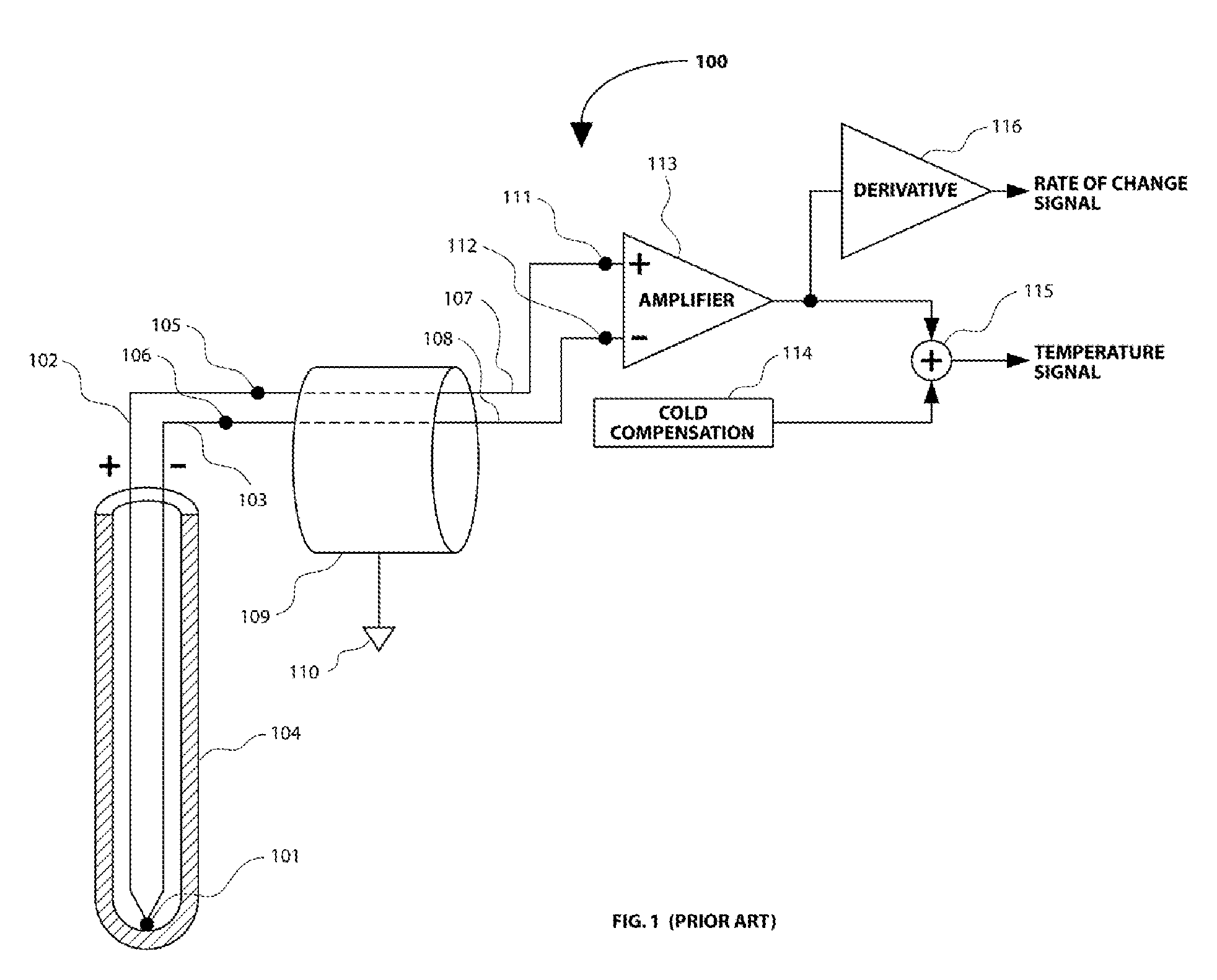
[0026]Turning now to the drawings and with particular attention to FIG. 1, a thermocouple measuring circuit according to prior art is shown. Prior art thermocouple measuring circuit 100 includes a thermocouple measuring junction 101, coupled to a positive thermocouple lead 102 and a negative thermocouple lead 103. The thermocouple measuring junction 101 and a portion of the positive thermocouple lead 102 and the negative thermocouple lead 103 are surrounded by a metal protection tube 104. The thermocouple measuring junction 101 is in contact with the protection tube 104 in this example. However, any of the thermocouple configurations that are known in prior art could be used for this measuring circuit and the following embodiments of the invention, including thermocouple configurations where the measuring junction is not in contact with the protection tube, is exposed outside of the protection tube, or where a protection tube is not used.

[0027]The positive thermocouple lead 102 is c...


PUM

PropertyMeasurementUnit
time lagaaaaaaaaaa
temperatureaaaaaaaaaa
thermoelectric voltageaaaaaaaaaa

Abstract

A method and apparatus is presented for obtaining of accurate measurements of the temperature of a thermocouple and high fidelity measurements of the rate of change of the temperature of a thermocouple. A first sub-circuit is connected to the thermocouple with two conductors made of two different thermocouple alloys which are substantially the same as the alloys used in the construction of the thermocouple. A second sub-circuit is connected to the thermocouple with two conductors made of substantially identical material, such as copper. The first sub-circuit provides an accurate measurement of the temperature of the thermocouple. The second sub-circuit provides a high fidelity measurement of the rate of change of the temperature of the thermocouple.

Description

CROSS-REFERENCE TO RELATED APPLICATIONS[0001]This application claims the benefit of Provisional Patent Application No. 61 / 398,922 filed Jul. 06, 2010.STATEMENT REGARDING FEDERALLY SPONSORED RESEARCH OR DEVELOPMENT[0002]Not ApplicableREFERENCE TO SEQUENCE LISTING, A TABLE, OR A COMPUTER PROGRAM LISTING COMPACT DISK APPENDIX[0003]Not ApplicableBACKGROUND OF THE INVENTION[0004]This invention relates to measuring temperature by the use of thermocouples. More particularly, this invention relates to thermocouple measuring devices and methods used to measure the rate of change of the temperature of the thermocouple.[0005]Thermocouples are constructed of two dissimilar metals (typically wires) joined together at a measurement junction. As is well known, thermocouples produce a small output voltage (referred to as the “thermoelectric voltage”) that is proportional to the temperature difference between the measurement junction and a reference junction. The reference junction is often referred...

Claims


Application Information

Patent Timeline
Patent Type & Authority Patents(United States)
IPC IPC(8): G01K3/00G01K7/00
CPCG01K3/10G01K7/02
Inventor GARDINER, DAVID PHILLIP
Owner GARDINER DAVID PHILLIP
Learn More