Agitation device, melting apparatus and melting method

a technology of agitation device and melting apparatus, which is applied in the direction of checking device, nuclear engineering, nuclear elements, etc., can solve the problems of reducing the quality of molten metal, troublesome maintenance, and wear of the implement and the propeller, and achieves high melting efficiency

Active Publication Date: 2013-12-03
TOYOTA JIDOSHA KK
View PDF18 Cites 4 Cited by
  • Summary
  • Abstract
  • Description
  • Claims
  • Application Information

AI Technical Summary

Benefits of technology

[0050]The present invention does not pollute molten metal and brings high melting efficiency.

Problems solved by technology

However, in the methods (1) and (2), the implement and a propeller touch the molten metal with high temperature, whereby the implement and the propeller are worn.
Therefore, it is necessary to exchange the implement and the propeller frequently, whereby the maintenance is troublesome.
In the methods (1) and (2), components of the broken implement or propeller may be mixed with the molten metal, thereby reducing the quality of the molten metal (the components may pollute the molten metal).
Generally, when the aluminium metal cutting chips are introduced to the vortex generated in the liquid surface, the aluminium metal cutting chips float on the liquid surface of the molten metal and are not rolled up by the molten metal successfully, whereby the cutting chips are hardly melted.
However, for generating strong vortex, it is necessary to make the sectional area of the opening of the bottom of the vortex generating chamber small to some degree.
When a large quantity of the aluminium metal cutting chips are introduced to the molten metal at once, the unmelted aluminium metal cutting chips rush in the opening and clog the opening.
Therefore, the processing speed (melting amount per unit time) of the aluminium metal cutting chips cannot be made very large.

Method used


Image

  • Agitation device, melting apparatus and melting method
  • Agitation device, melting apparatus and melting method
  • Agitation device, melting apparatus and melting method

Examples


first embodiment

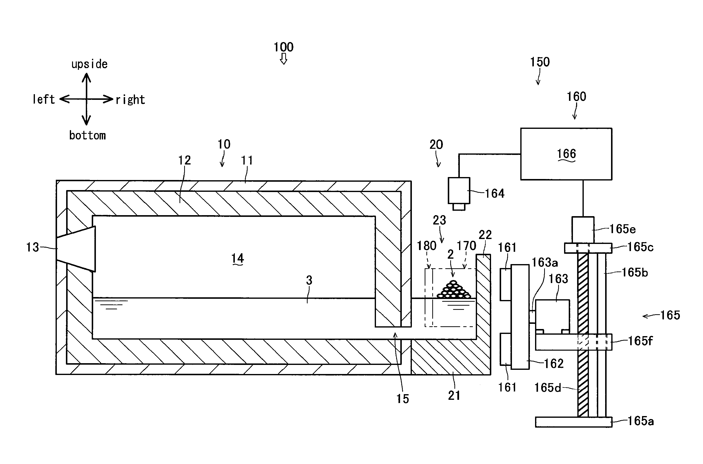
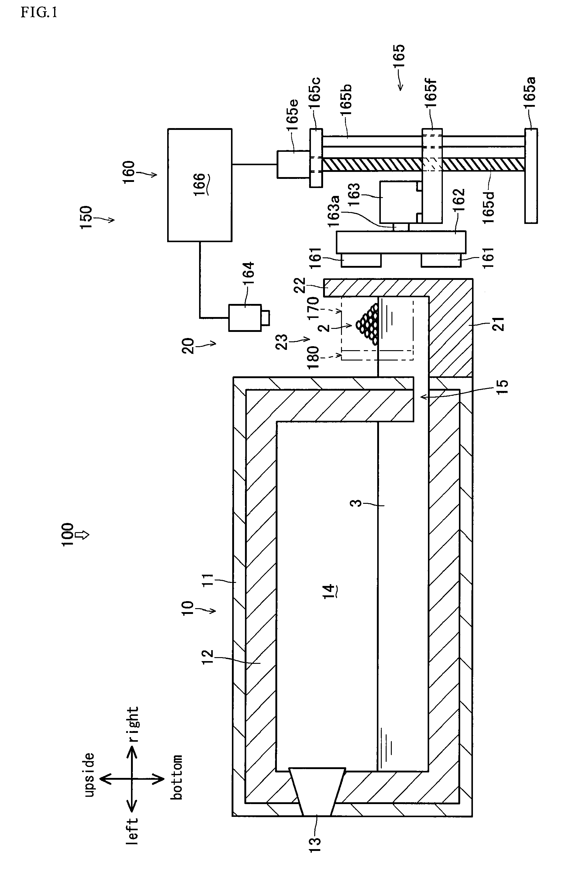
[0085]Explanation will be given on a melting furnace 100 which is a melting apparatus according to the present invention referring to FIGS. 1 to 6.

[0086]For convenience, hereinafter, “vertical direction” is defined on the basis of the direction of gravity (the direction of gravity is defined as the downward), “longitudinal direction” is defined as the direction perpendicular to the vertical direction, “lateral direction” is defined as the direction perpendicular to the vertical direction and the longitudinal direction, and these directions are employed in the explanation.

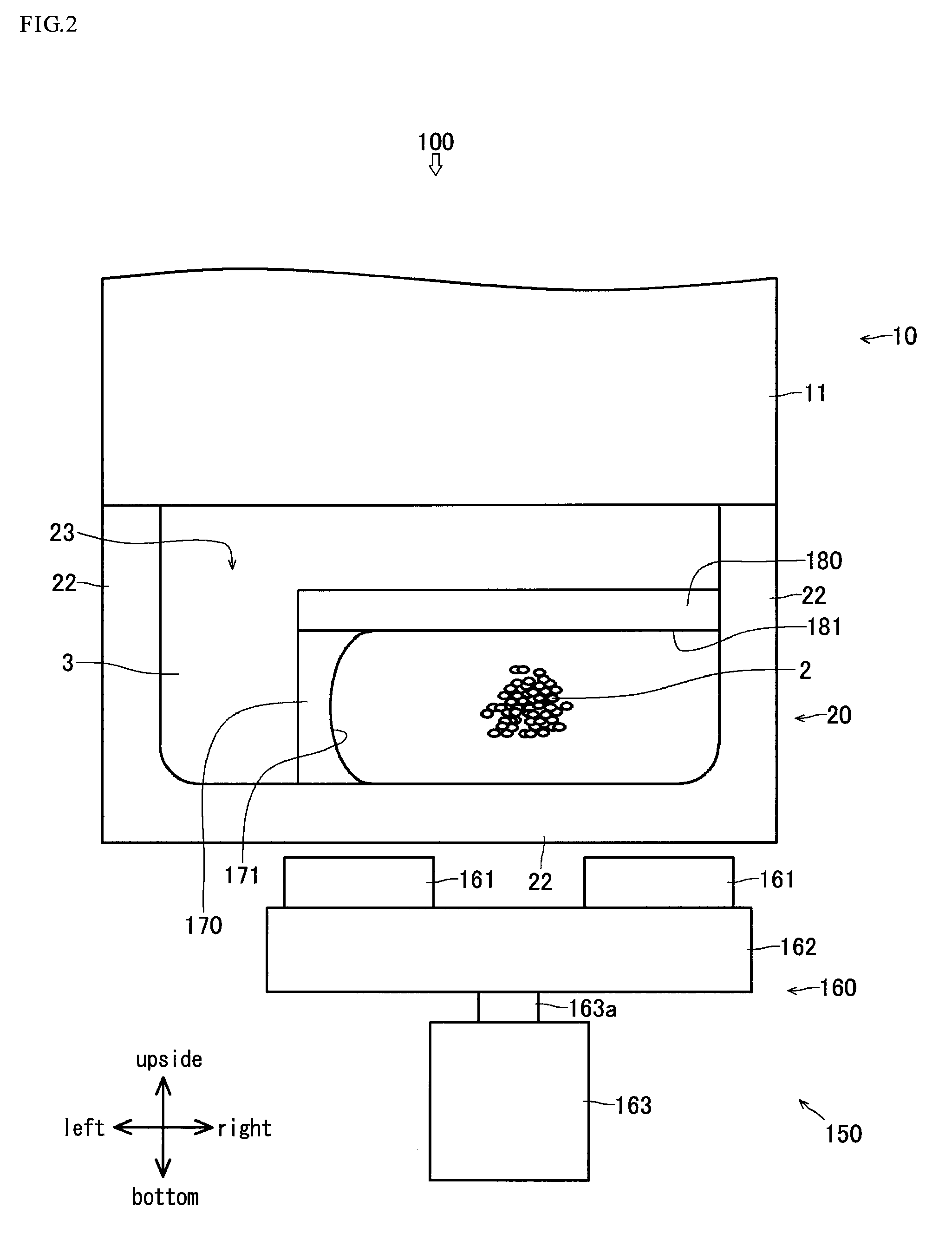
[0087]As shown in FIG. 1, the melting furnace 100 generates molten metal 3 by melting aluminum cutting chips 2 and has a main body 10, a charging tank 20 and an agitation device 150.

[0088]The aluminum cutting chips 2 are an embodiment of melted matter according to the present invention and is an object melted by the melting furnace 100. The aluminum cutting chips 2 include aluminum alloy. The aluminum cutting chips ...

second embodiment

[0216]Explanation will be given on a melting furnace 200 which is the melting apparatus according to the present invention referring to FIGS. 7 and 8.

[0217]In below explanation, for convenience, the construction of the melting furnace 200 which is the same as the construction of the melting furnace 100 shown in FIG. 1 is designated by the same reference numeral and description thereof is omitted.

[0218]As shown in FIG. 7, the melting furnace 200 has the main body 10, the charging tank 20 and an agitation device 250.

[0219]The agitation device 250 is a second embodiment of the agitation device according to the present invention and agitates the molten metal 3 to which the aluminum cutting chips 2 are introduced (the molten metal 3 stored in the lower half of the charging chamber 23) so as to promote melting of the aluminum cutting chips 2.

[0220]As shown in FIGS. 7 and 8, the agitation device 250 has a traveling magnetic field generating unit 260, a first molten metal straightening memb...

third embodiment

[0253]Explanation will be given on a melting furnace 300 which is the melting apparatus according to the present invention referring to FIGS. 11 to 15.

[0254]In below explanation, for convenience, the construction of the melting furnace 300 which is fundamentally the same as the construction of the melting furnace 100 shown in FIG. 1 is designated by the same reference numeral and description thereof is omitted.

[0255]As shown in FIG. 11, the melting furnace 300 has the main body 10, the charging tank 20 and an agitation device 350.

[0256]The agitation device 350 is a third embodiment of the agitation device according to the present invention and agitates the molten metal 3 to which the aluminum cutting chips 2 are introduced (the molten metal 3 stored in the lower half of the charging chamber 23) so as to promote melting of the aluminum cutting chips 2.

[0257]As shown in FIG. 11, the agitation device 350 has a traveling magnetic field generating unit 360 and an introduced / suspended mat...


PUM

PropertyMeasurementUnit
lengthaaaaaaaaaa
sizeaaaaaaaaaa
sizeaaaaaaaaaa

Abstract

An agitation device, a melting apparatus, and a melting method for improving melting efficiency of molten metal without contaminating the same. The agitation device is provided with a traveling magnetic field generating unit which is disposed outside a charging tank for storing molten metal and generates, inside the charging tank, a magnetic field that travels downward along the rear sidewall of the charging tank. A flow of the molten metal that rotates longitudinally about an axis approximately parallel to the surface of the molten metal is produced in the molten metal. By charging aluminum cutting chips into the molten metal in which the flow is produced, the aluminum cutting chips move with a downward flow of the molten metal, and are immersed in the molten metal. As a result, melting of the aluminum cutting chips can be accelerated.

Description

[0001]This is a 371 national phase application of PCT / JP2009 / 005655 filed 27 Oct. 2009, claiming priority to Japanese Patent Applications No. 2008-278106 filed 29 Oct. 2008, No. 2009-141517 filed 12 Jun. 2009, and No. 2009-205091 filed 04 Sep. 2009, respectively, the contents of which are incorporated herein by reference.TECHNICAL FIELD[0002]The present invention relates to an agitation device in which a melted matter (for example, cutting chips of nonferrous metal such as aluminum or magnesium) is introduced to molten metal and the molten metal is agitated, a melting apparatus having such agitation device, and a melting method in which a melted matter is introduced to molten metal and the molten metal is agitated so as to melt the melted matter.BACKGROUND ART[0003]There are conventional arts as methods for melting cutting chips of nonferrous metal such as aluminum or magnesium by introducing them to molten metal and agitating the molten metal: (1) a method in which the cutting chip...

Claims


Application Information

Patent Timeline
Patent Type & Authority Patents(United States)
IPC IPC(8): F27D27/00G21C7/00F27D3/00
CPCB22D1/00B22D46/00C22B9/003F27D27/00C22B21/0092F27B3/10F27B3/205C22B21/0084Y02P10/20Y02P10/25
Inventor KORIYAMA, SHINICHIHIRAI, TAKASHI
Owner TOYOTA JIDOSHA KK
Why Eureka
Try Eureka