
Method for high-resolution detection of nanoparticles on two-dimensional detector surfaces

a detector surface and nanoparticle technology, applied in the field of surface plasmon resonance microscope, can solve the problem that individual particles cannot be detected with this method, and achieve the effect of a strong change of reflectivity

Active Publication Date: 2013-11-19
LEIBNIZ INST FUER ANALYTISCHE WISSENSCHAFTEN ISAS EV
View PDF9 Cites 3 Cited by
  • Summary
  • Abstract
  • Description
  • Claims
  • Application Information

AI Technical Summary

Benefits of technology

The invention is about a method and assembly for detecting individual nanoparticles, particularly viruses, with higher resolution than classical optical detection. The resolution is achieved by higher lateral resolution of the detector and by using a reference image to correct the background signal. The method can detect particles as small as 40 nm and can be used in virological research and clinic diagnostics. The invention also provides a surface with strong changes in reflectivity that can be used for characterizing particles.

Problems solved by technology

Individual particles cannot be detected with this method because the signal integrated over a relative large area is detected.

Method used


Image

  • Method for high-resolution detection of nanoparticles on two-dimensional detector surfaces
  • Method for high-resolution detection of nanoparticles on two-dimensional detector surfaces
  • Method for high-resolution detection of nanoparticles on two-dimensional detector surfaces

Examples


Embodiment Construction

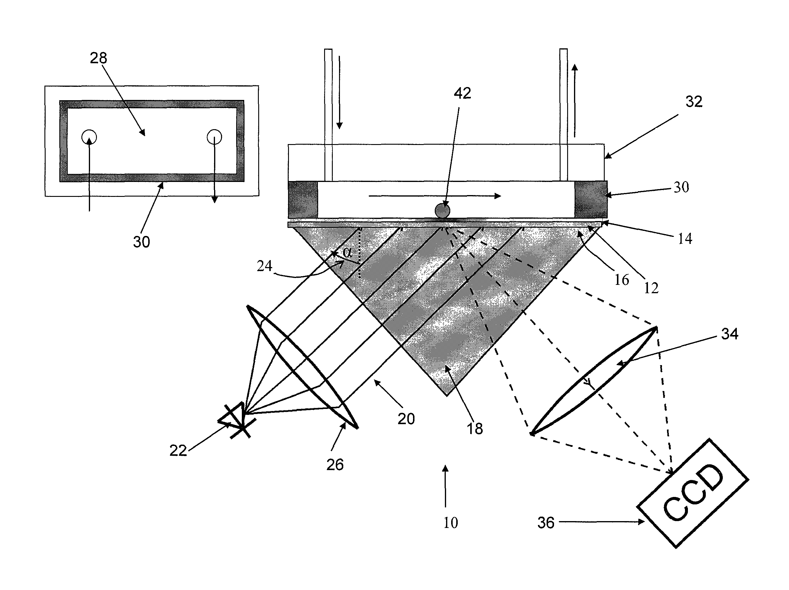
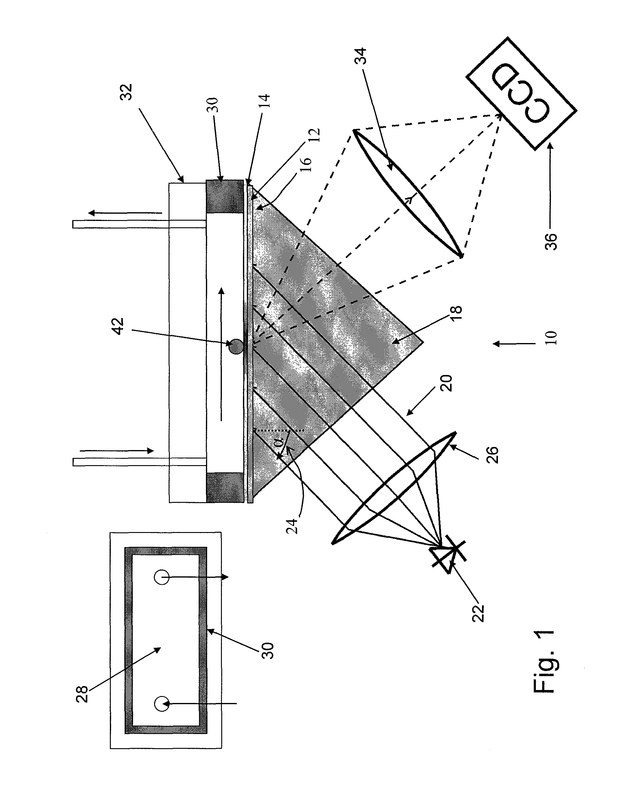
[0043]FIG. 1 shows a Kretschmann assembly in imaging configuration which is generally denoted with numeral 10. Such an assembly 10, as such, is known. The way of operation of a surface plasmon spectrometer, therefore, need not be described here in greater detail. A glass plate 12 is coated with a 50 nm gold layer 14. The side 16 of the glass plate 12 opposite to the gold layer 14 is fixed to a prism 18. Immersion oil is used for fixing and improving the optical contact.

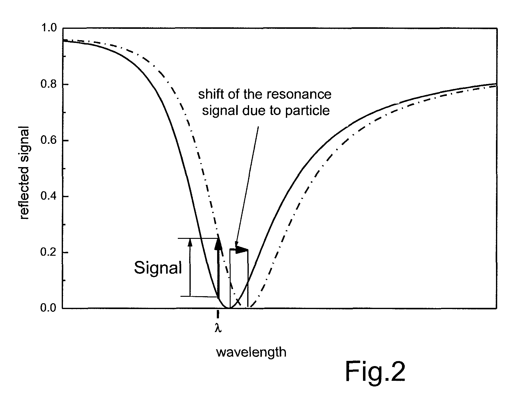
[0044]The gold layer 14 is illuminated with radiation 20 from a superluminescent diode 22. An example for a suitable diode 22 is a QSDM-680-9 by Qphotonix emitting at a wavelength of about 670 nm, in the visible range. The illumination is effected through prism 18 with fixed incident angle 24. Contrary to a Laser as a radiation source, a superluminescent diode has no irregularities on the illuminated surface (speckles). The incident angle 24 is selected on the left side of the resonance minimum, i.e. with a smaller an...


PUM

PropertyMeasurementUnit
diameteraaaaaaaaaa
diameteraaaaaaaaaa
diameteraaaaaaaaaa

Abstract

The invention relates to a surface plasmon resonance spectrometer comprising a radiation source that emits substantially monochromatic radiation, a sensor surface, an optical arrangement for lighting the sensor surface by the radiation emitted from the radiation source such that surface plasmons can be created in the sensor surface, a detector having a plurality of image elements and observation optics for depicting the radiation reflected by the sensor surface on the detector, characterized in that the resolution capability of the observation optics and of the detector is larger than the resolution that can be obtained by the deflection-limited radiation source.

Description

RELATED APPLICATIONS[0001]This application is a continuation-in-part of International Application PCT / EP2010 / 052229 filed Feb. 23, 2010, and which specified the United States, and which is based on and claims priority to German Application DE 10 2009 003 548.6 filed Feb. 27, 2009.TECHNICAL FIELD[0002]The invention relates to a surface plasmon resonance microscope, comprising[0003](a) a radiation source emitting essentially monochromatic radiation,[0004](c) a sensor surface,[0005](b) an optical assembly for illuminating the sensor surface with the radiation emitted by the radiation source in such a way that surface plasmons are generated in the sensor surface,[0006](d) a detector with a plurality of detector elements, and[0007](e) an observation optical assembly for imaging the radiation reflected by the sensor surface on the detector.[0008]The invention also relates to a method for the optical detection of individual nanoparticles bound to two-dimensional sensor surfaces or present ...

Claims


Application Information

Patent Timeline
Patent Type & Authority Patents(United States)
IPC IPC(8): G01N21/55
CPCG01N15/1463G01N21/553G02B21/0008G02B21/008G01N21/55G01N21/554G01N2015/0038G01N2015/0088G01N2015/019G01N15/1433
Inventor ZYBIN, ALEXANDER
Owner LEIBNIZ INST FUER ANALYTISCHE WISSENSCHAFTEN ISAS EV
Learn More