
Electrosurgical generator

a generator and electrosurgical technology, applied in the field of electrosurgical generators, can solve the problems of tearing of tissue when the jaws are removed, not desirable to continue to apply current excessively, and each of the above systems has its own limitations, so as to prevent overheating and avoid tissue overheating and tissue damage.

Active Publication Date: 2013-11-19
GYRUS MEDICAL LTD
View PDF17 Cites 144 Cited by
  • Summary
  • Abstract
  • Description
  • Claims
  • Application Information

AI Technical Summary

Benefits of technology

The present invention relates to a method and generator for treating tissue with RF energy. The technical effects of the invention include maintaining the tissue at the boiling point of the electrolytes for a predetermined period of time, without overheating or damaging the tissue, and providing an indication to the user when the treatment is complete. The generator can maintain the RF energy at a reduced power or voltage level for a further period of time to allow the tissue to cool and re-solidify before the jaws of the instrument are opened. This alternative arrangement helps produce effective tissue sealing without tearing. The user can set the timer to determine the duration of the treatment.

Problems solved by technology

It is essential to apply the coagulating current signal for sufficient time to enable the tissue to be fully coagulated, but it is not desirable to continue to apply current excessively after the time that the tissue is coagulated.
Excessive application of a coagulating waveform will produce desiccation of the tissue, and it may become adhered to the jaws of the instrument, resulting in a tearing of the tissue when the jaws are removed.
However, due to the variation between different samples of tissue being coagulated, both in terms of thickness and composition, each of the above systems has its own limitations.

Method used


Image

  • Electrosurgical generator
  • Electrosurgical generator
  • Electrosurgical generator

Examples


Embodiment Construction

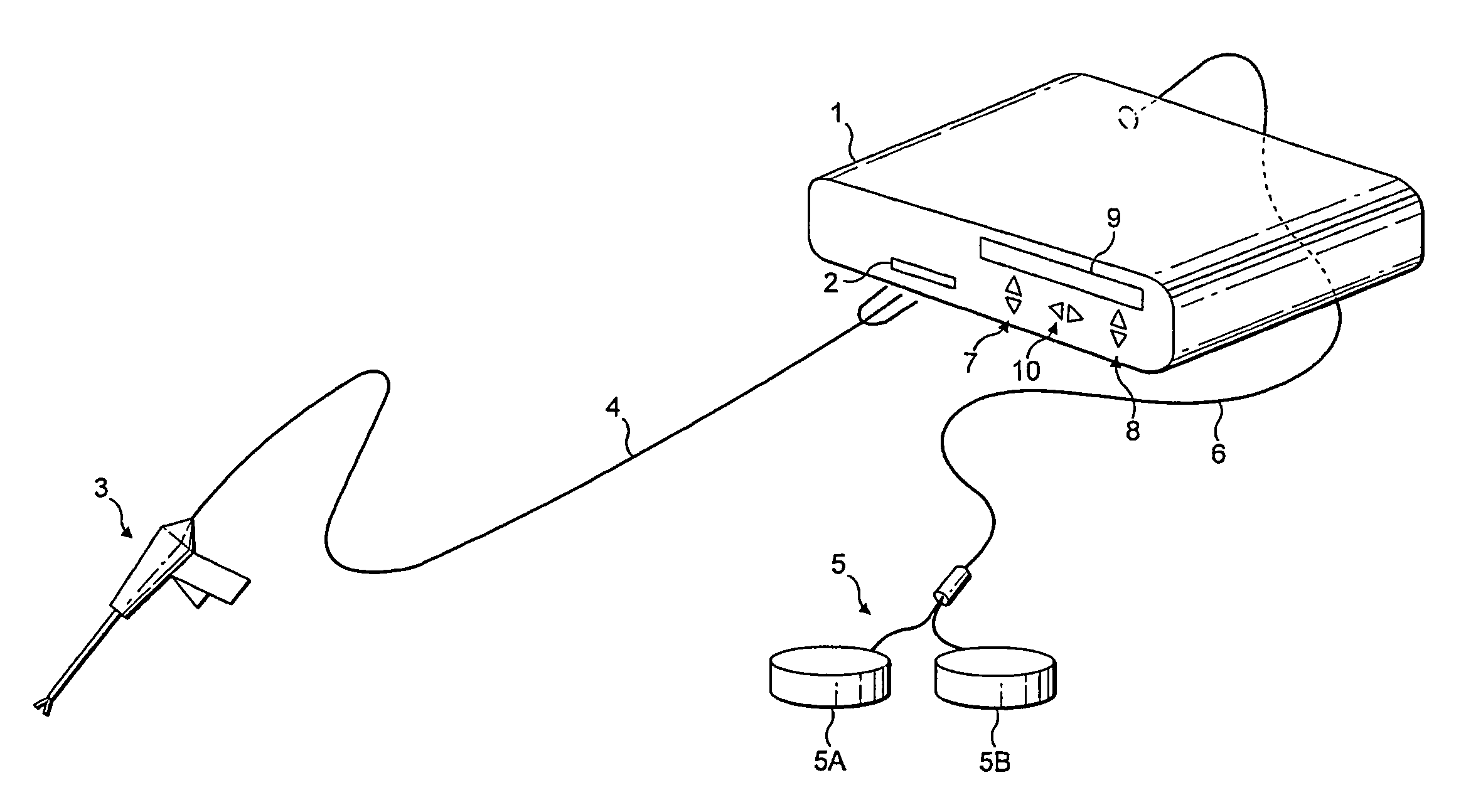
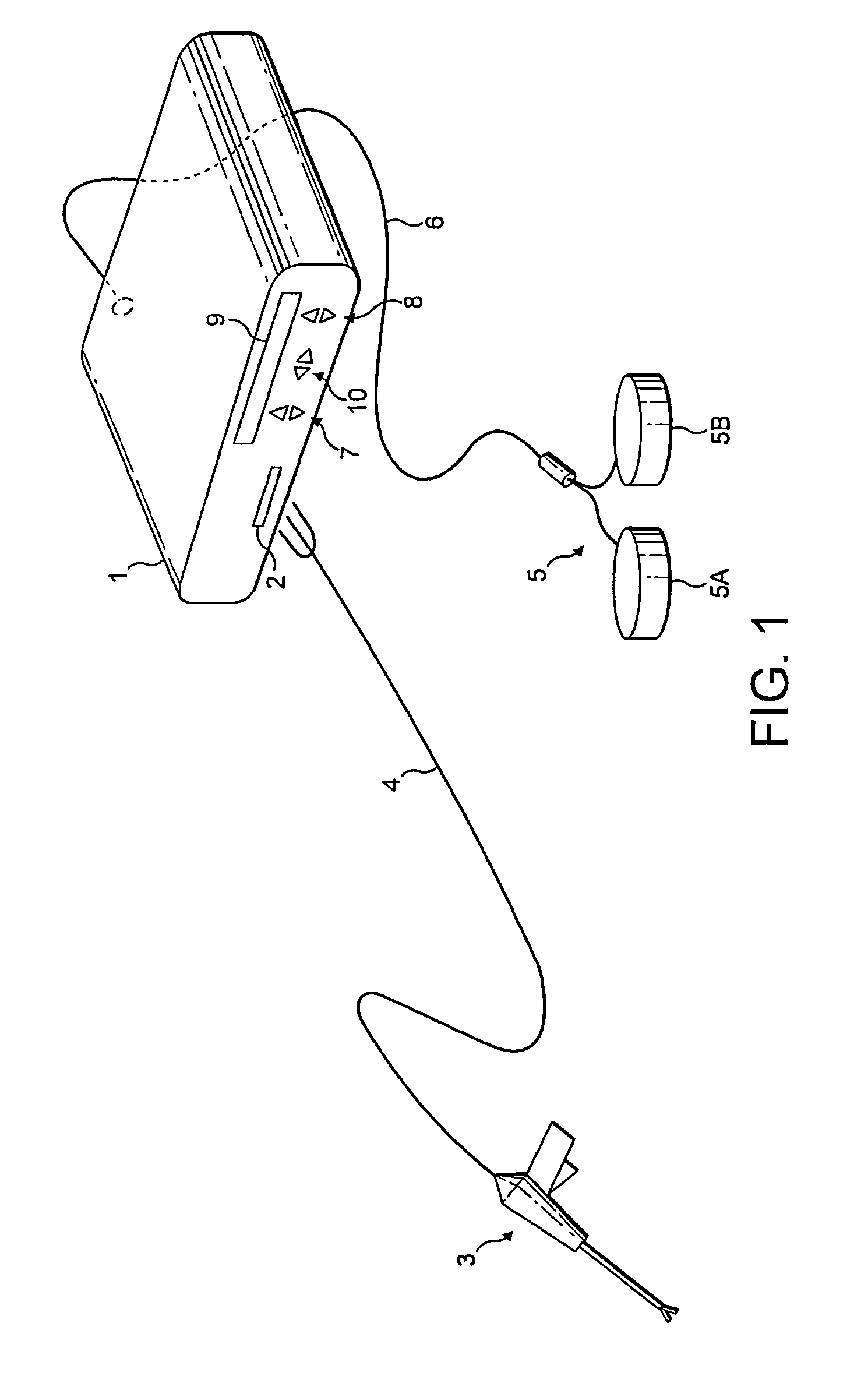
[0027]Referring to FIG. 1, a generator 1 has an output socket 2 providing a radio frequency (RF) output for an instrument 3 via a connection cord 4. Activation of the generator 1 may be performed from the instrument 3 via a connection in the cord 4, or by means of a footswitch unit 5, as shown, connected to the rear of the generator by a footswitch connection cord 6. In the illustrated embodiment, the footswitch unit 5 has two footswitches 5A, 5B for selecting a coagulation mode and a cutting mode of the generator 1 respectively. The generator front panel has push buttons 7, 8 for respectively setting coagulation and cutting power levels, which are indicated in a display 9. Push buttons 10 are provided as an alternative means for selection between coagulation and cutting modes.

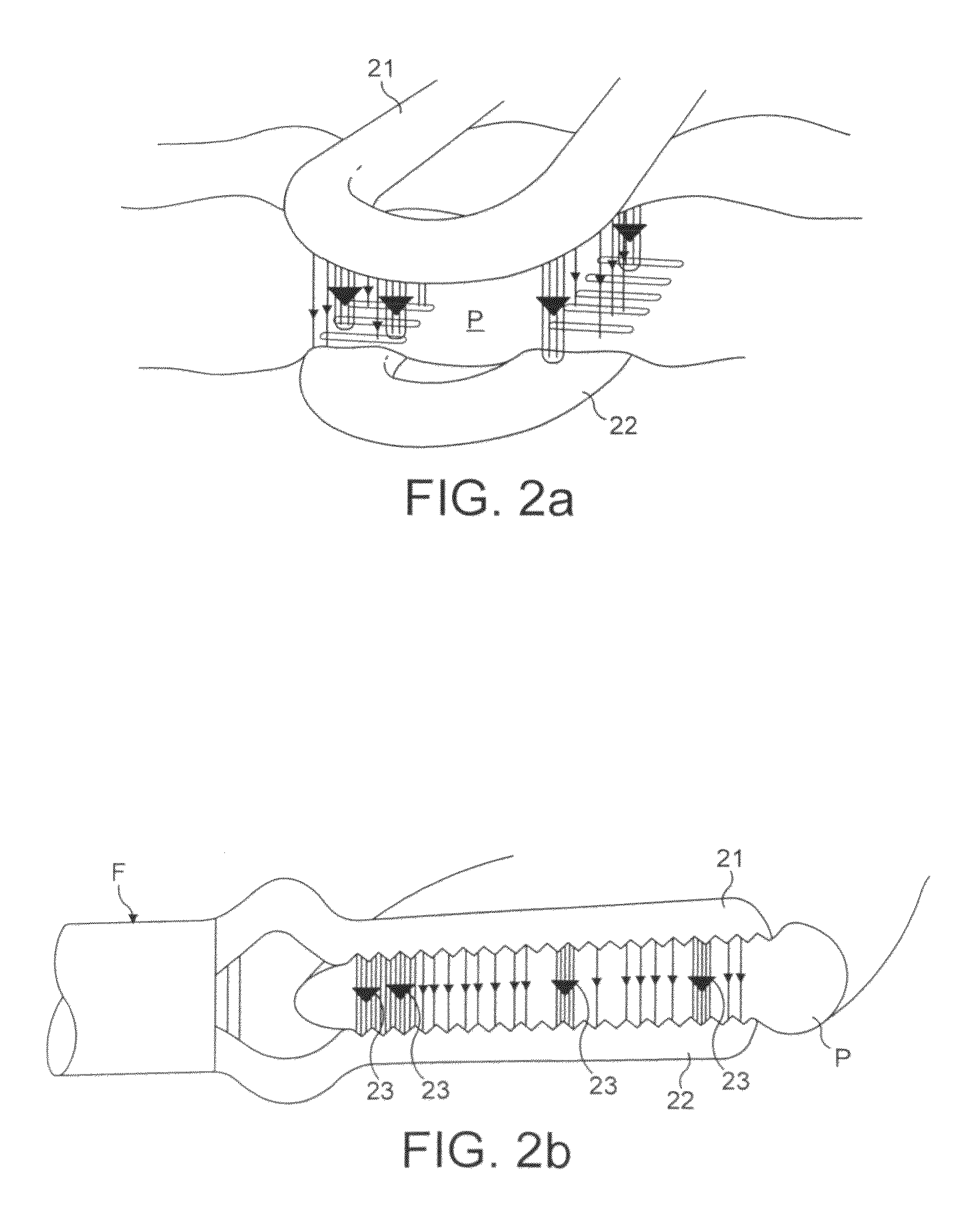
[0028]FIGS. 2a and 2b show a typical forceps device F, grasping a pedicle P of tissue between the jaws 21, 22 of the forceps F. These figures show different perspective views of the forceps F, respectively fro...


PUM


Abstract

An electrosurgical generator for coagulating tissue comprises a source of radio frequency (RF) energy, and at least a pair of output terminals for connection to a bipolar electrosurgical instrument adapted to contact tissue, the output terminals delivering RF energy from the source to the instrument such that the source delivers RF energy into tissue. The generator also includes boiling detection means for determining when the RF energy starts to cause the boiling of electrolytes within the tissue. A timer is adapted to determine when a predetermined period of time has elapsed since the boiling detection means has indicated the start of the boiling of electrolytes. An indication means gives an indication when the predetermined period of time has elapsed.

Description

FIELD OF THE INVENTION[0001]This invention relates to an electrosurgical generator for use in the sealing of tissue, particularly blood vessels such as large veins and arteries.BACKGROUND OF THE INVENTION[0002]The coagulation of tissue, particularly the sealing or occlusion of vessels such as veins and arteries is an important feature of many surgical interventions. There is a range of equipment, both mechanical and electrosurgical, for sealing or clamping vascular tissue. In the electrosurgical field, it is typical for a jawed instrument to grasp tissue and deliver a coagulating radio frequency (RF) current. Prior art patents such as U.S. Pat. No. 6,893,435, and U.S. Pat. No. 6,743,229 disclose examples of this type of system. The subject matter of U.S. Pat. No. 6,893,435 is hereby specifically incorporated in the present application by reference.[0003]It is essential to apply the coagulating current signal for sufficient time to enable the tissue to be fully coagulated, but it is ...

Claims


Application Information

Patent Timeline
Patent Type & Authority Patents(United States)
IPC IPC(8): A61B18/14
CPCA61B18/1445A61B2018/00589A61B2018/00666A61B2018/00702A61B2018/00761A61B2018/00875A61B2018/00886A61B18/1206A61B18/1442
Inventor AMOAH, FRANCISWILLIAMS, WAYNE
Owner GYRUS MEDICAL LTD
Learn More