
Method and device for controlling the regeneration of a particulate filter

a technology of particulate filter and regeneration method, which is applied in the direction of exhaust treatment, mechanical equipment, engine components, etc., can solve the problems of ineffective, inconvenient operation, and ineffective regeneration of particulate filter, and achieve the effect of advantageous installation

Inactive Publication Date: 2013-11-19
PIRELLI & C ECO TECH
View PDF15 Cites 3 Cited by
  • Summary
  • Abstract
  • Description
  • Claims
  • Application Information

AI Technical Summary

Benefits of technology

The patent text describes a system for regenerating a filter that reduces emissions in vehicle exhaust gases. The system uses heating devices that are activated periodically to burn off the filter's accumulated particulate matter (PM) without causing excessive wear and tear on the heating devices. As a result, the system can be installed in a variety of vehicle types without needing major modifications, and can be sold as an aftermarket product. The technical effect of the system is to reduce emissions from vehicle exhaust gases without causing excessive wear and tear on the regeneration system.

Problems solved by technology

However, the Applicant has observed that the known solutions for performing the particulate filter regeneration are not efficient, being expensive, energy consuming for the vehicle, and not always useful.
Indeed, with the solutions already known in the art, the burning of the PM retained by the filter may be triggered when it is not really necessary, or even it may not succeed.
This is a great drawback, since the activation of the heating devices consumes a non-negligible electric power, that in this case is entirely wasted.
Wasting the already limited vehicle battery power is highly undesirable.
Moreover, even if the temperature of the exhaust gas is sufficiently high, a periodical activation of the heating devices may trigger the burning of the PM too often, even when it is not necessary, for example because the PM included in the DPF is relatively small.
This drawback is exacerbated by the fact that the periodical activation of the heating devices may shorten the operative life of the heating devices themselves.

Method used


Image

  • Method and device for controlling the regeneration of a particulate filter
  • Method and device for controlling the regeneration of a particulate filter
  • Method and device for controlling the regeneration of a particulate filter

Examples


Embodiment Construction

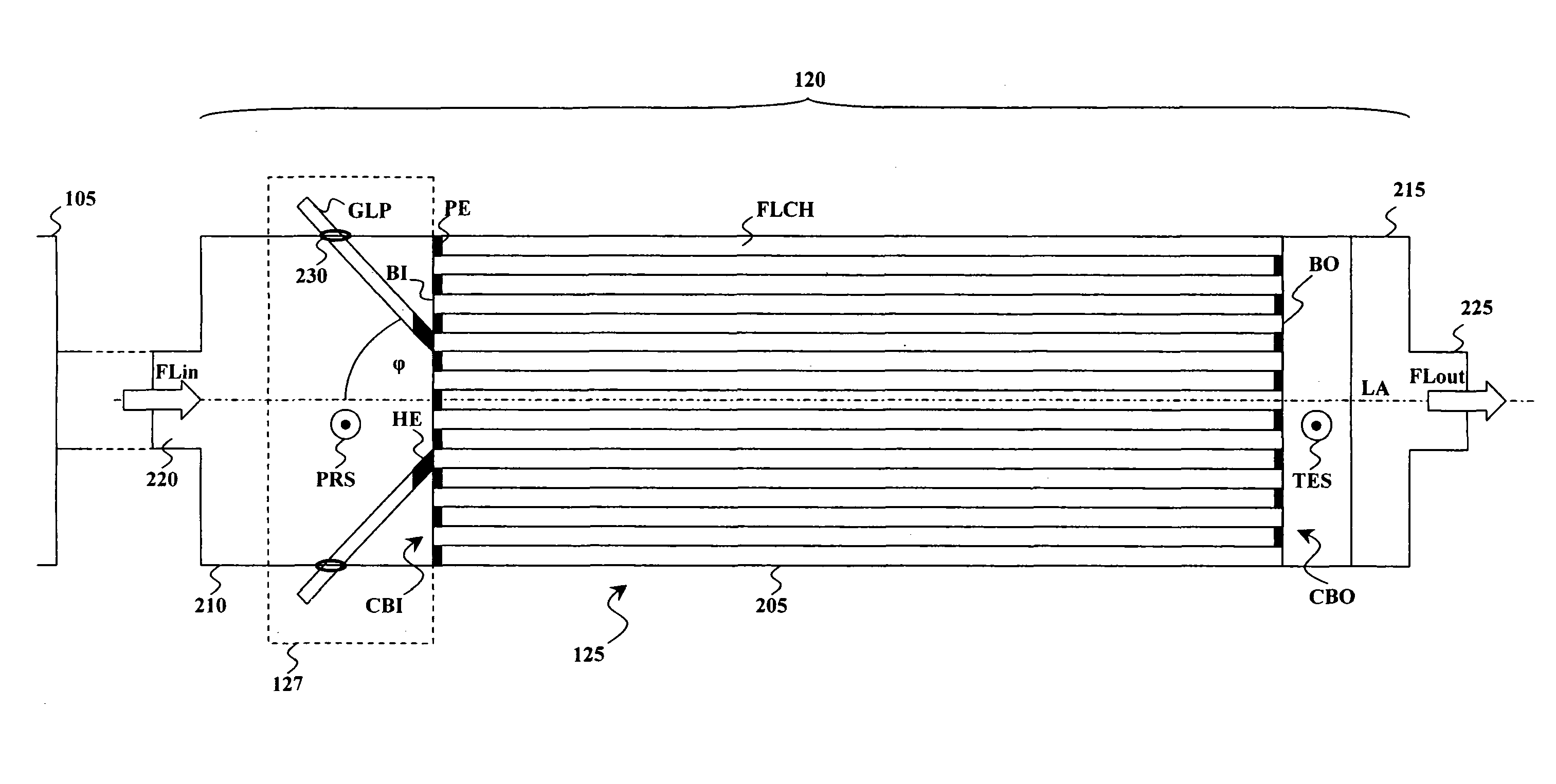
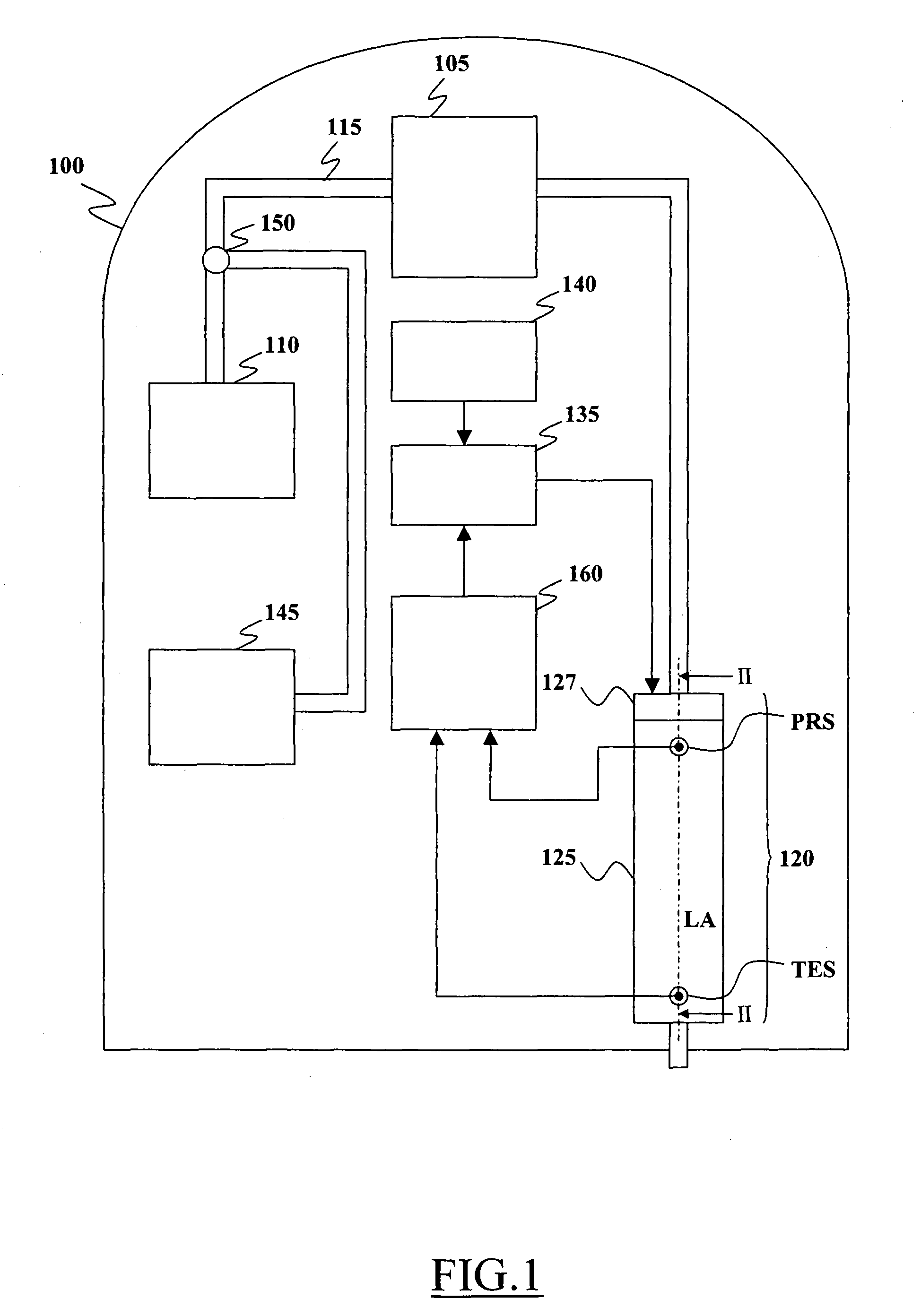
[0108]With reference to the drawings, FIG. 1 illustrates in terms of schematic blocks a possible application of a filter regeneration control system according to an embodiment of the present invention.

[0109]More particularly, in the scenario illustrated in FIG. 1, a vehicle 100, for example a car or a van, is equipped with an engine 105, for example of the diesel type, which generates kinetic energy for moving the vehicle 100. The vehicle 100 further includes a fuel tank 110 adapted to store fuel, such as gas oil; the fuel stored in the fuel tank 110 is supplied to the engine 105 through a fuel pipe 115, for being combusted in the engine 105 in order to generate the kinetic energy that causes the vehicle 100 to move.

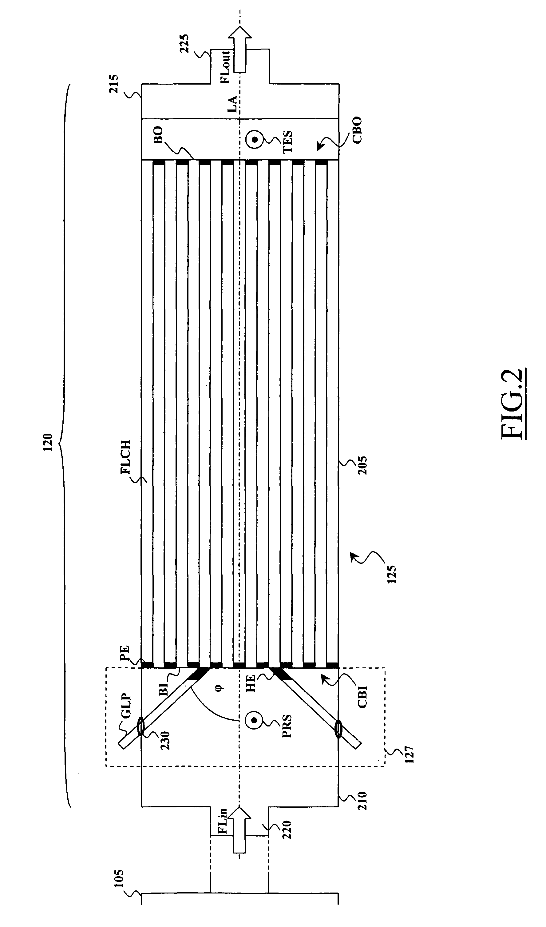
[0110]The combustion process of the fuel occurring in the engine 105 produces exhaust gas, which is evacuated to the outside of the vehicle 100 through a car exhaust device 120; particularly, the car exhaust device 120 comprises a Diesel Particulate Filter (DPF) 125 prov...


PUM


Abstract

A method of controlling the regeneration of a particulate filter adapted to filter particulate matter present in exhaust emissions of an engine of a vehicle. The particulate filter is coupled to a heating device adapted to be activated so as to cause the heating of the particulate filter. The method includes sensing at least one operating parameter of the particulate filter, receiving sensed data relating to the at least one sensed operating parameter and conditioning the activation of the heating device based on a comparison of the received data with at least one respective threshold. The method further includes adjusting a value of the at least one threshold based on an operating condition of the vehicle, the operating condition being detected based on the received sensed data.

Description

CROSS REFERENCE TO RELATED APPLICATION[0001]This application is a national phase application based on PCT / IT2008 / 000541, filed Aug. 8, 2008, the content of which is incorporated herein by reference.FIELD OF THE INVENTION[0002]The present invention relates to the field of the devices for filtering exhaust gas emissions. Particularly, the present invention relates to a method and device for regenerating filters of particulate emissions produced by combustion processes, like those occurring in a diesel engine.BACKGROUND OF THE INVENTION[0003]With the term “exhaust gas” it is intended a flue gas that is produced as a result of the combustion of fuels, such gasoline / petrol, diesel, fuel oil or coal. The ever increasing diffusion of power plants, industrial process plants, and motor vehicles in the world, has urgently led to the study of possible solutions for reducing the harmful effects of the exhaust gases on the environment and on the man.[0004]Indeed, although the largest part of mos...

Claims


Application Information

Patent Timeline
Patent Type & Authority Patents(United States)
IPC IPC(8): F01N3/00F01N3/02
CPCF01N3/027F01N9/002F01N9/007F01N11/002F01N3/0256Y02T10/47F01N2240/16F01N2560/06F01N2560/08F01N2900/0402Y02T10/40
Inventor ARRIGONI, GABRIELEACCORRA', MATTEOFEDELI, DAVIDE
Owner PIRELLI & C ECO TECH
Learn More