
Rechargeable flameless candle systems and methods

a flameless candle and rechargeable technology, applied in the direction of electric lighting, decorative arts, electric lighting with built-in generators, etc., can solve the problems of limited counter or shelf space available for recharge, inconvenient orienting a flameless candle in a specific manner, and unwise to leave lit candles unattended, so as to improve the electrical connection

Active Publication Date: 2013-11-12
STERNO HOME INC
View PDF14 Cites 21 Cited by
  • Summary
  • Abstract
  • Description
  • Claims
  • Application Information

AI Technical Summary

Benefits of technology

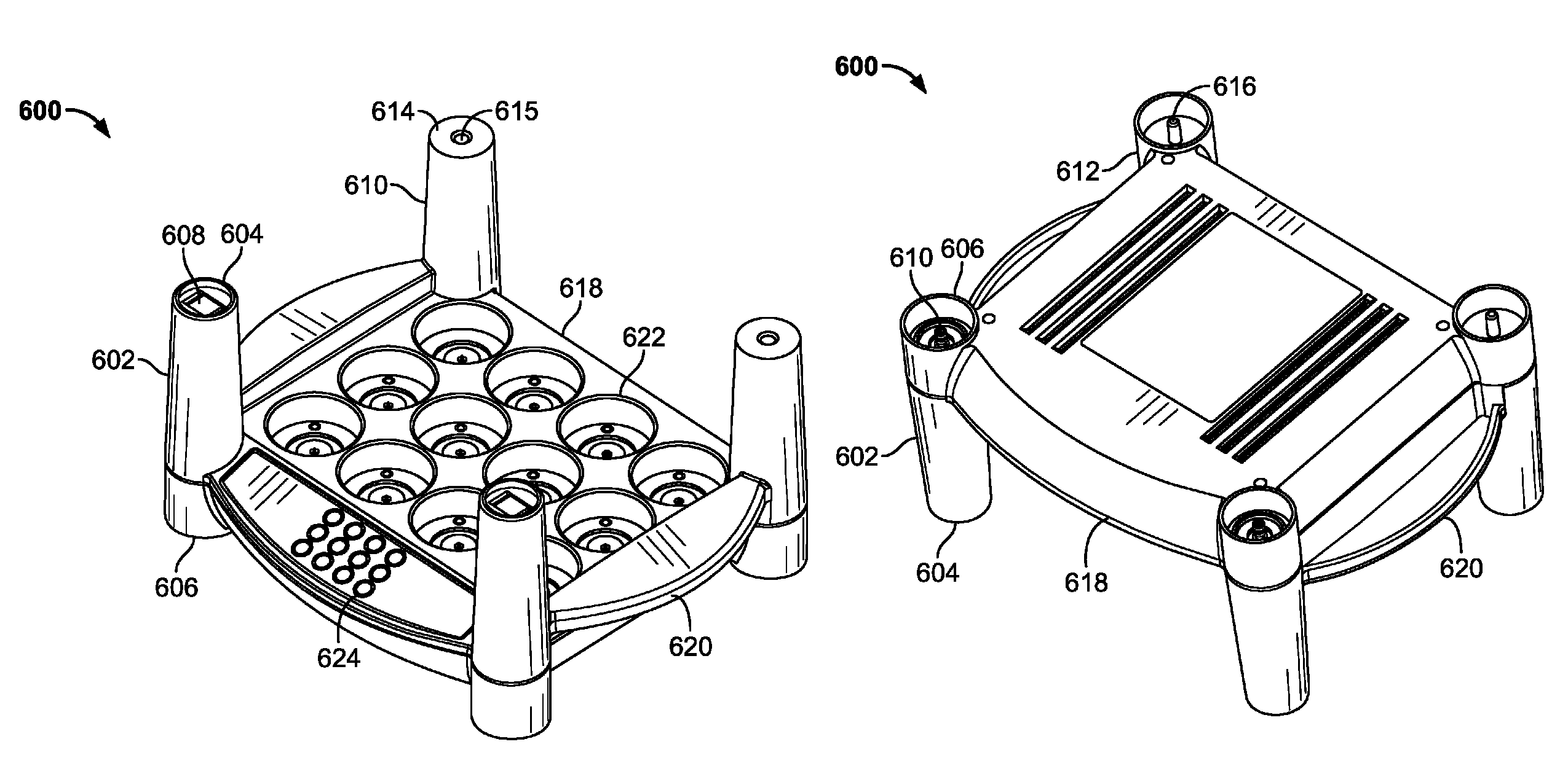
The present invention relates to a flameless candle that includes a lamp and a battery electrically connected with the lamp. The flameless candle also has outer and inner magnetically responsive portions that help connect the candle to an external power source. The flameless candle also has a recharging port that can be used to recharge the battery. A recharging device includes a recharging port and a tray with handles for easy handling of the flamless candle. The invention also includes a method for recharging the flamless candle by stacking and unStacking the recharging devices. The technical effects of the invention include improved safety, reduced risk of fire, and improved recharging efficiency.

Problems solved by technology

However there are certain risks associated with open flames, and it may be unwise to leave a lit candle unattended.
There may, however, be a limited amount of available counter or shelf space to recharge a number of flameless candles.
Furthermore, it may be inconvenient to orient a flameless candle in a specific manner when inserting it into a recharger.
Moreover, it may be inconvenient to recharge larger candles, such as flameless pillar candles.

Method used


Image

  • Rechargeable flameless candle systems and methods
  • Rechargeable flameless candle systems and methods
  • Rechargeable flameless candle systems and methods

Examples


Embodiment Construction

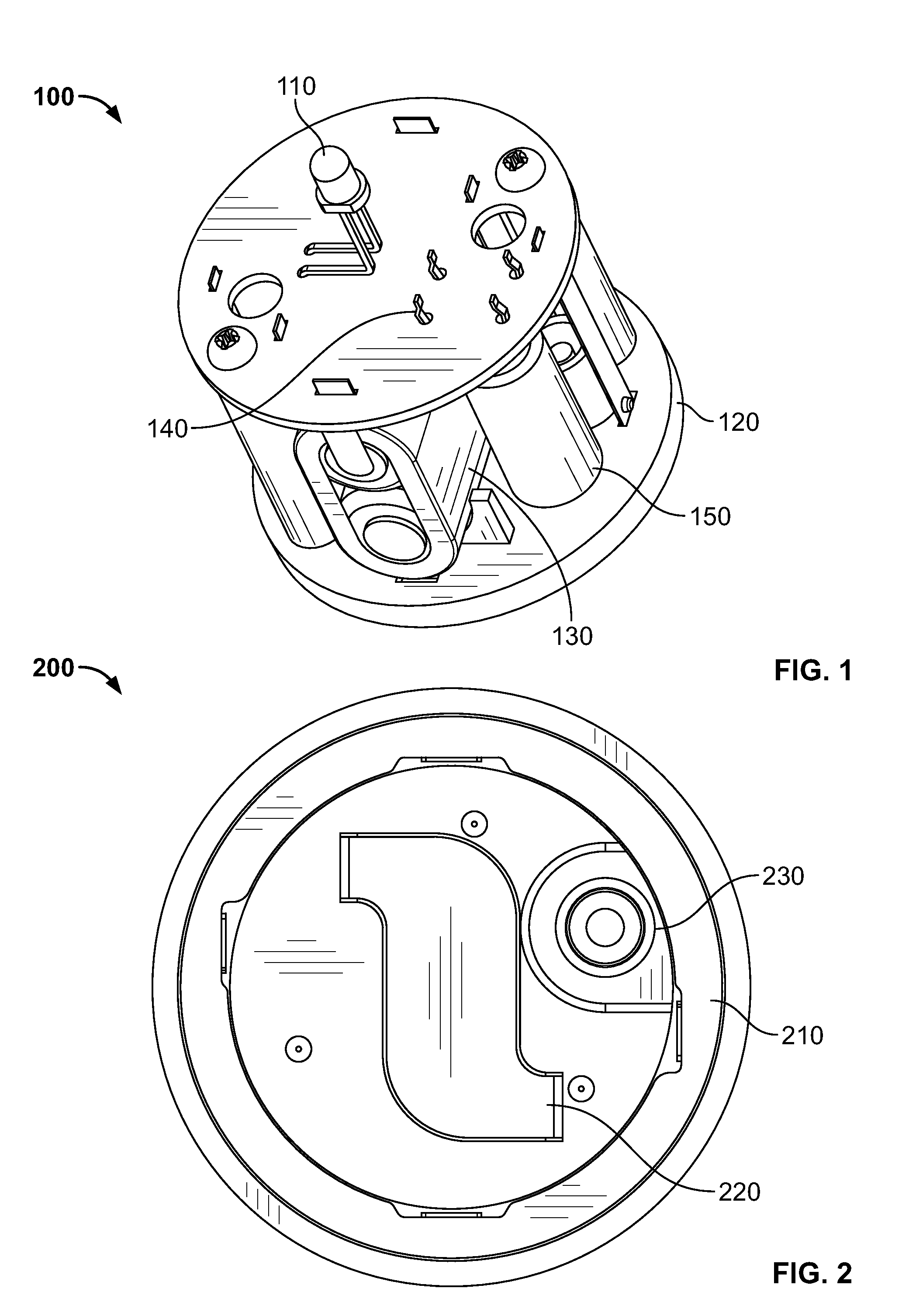
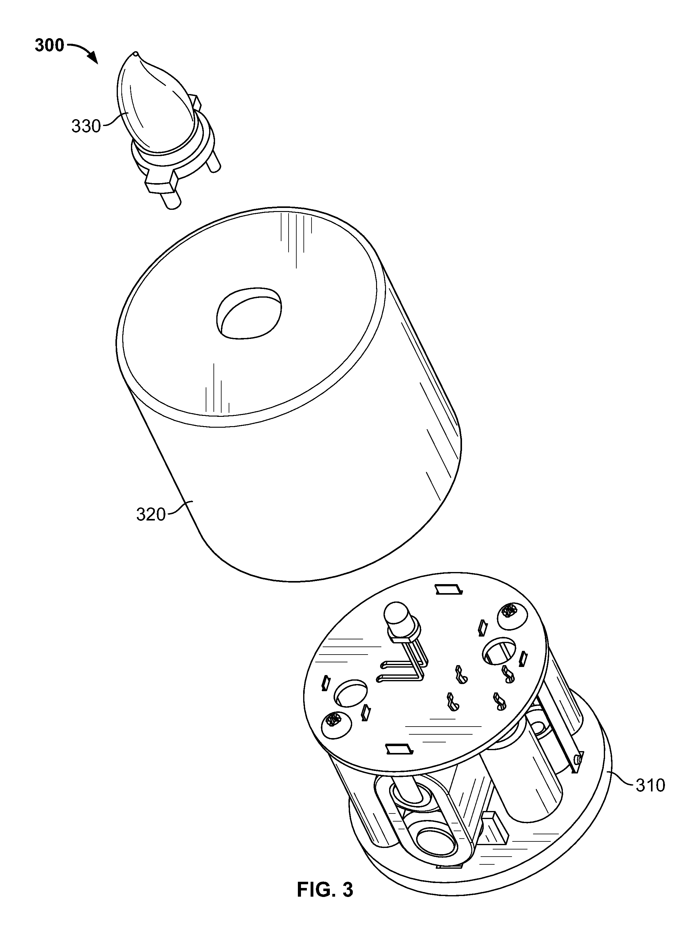
[0026]FIG. 1 shows a flameless candle core 100 including a lamp 110, a bottom portion 120, a rechargeable battery 130, an electronics portion 140, and one or more risers 150, in accordance with an embodiment of the present invention. The flameless candle insert 100 may also include a switch (not shown).

[0027]The rechargeable battery 130 may be capable of powering the lamp 110 and a circuit on the electronics portion 140. The rechargeable battery 130 may include one or more battery cells. The rechargeable battery 130 may be nickel cadmium, nickel metal hydride, lithium ion, and / or other types of rechargeable batteries. In an embodiment of the present invention, the rechargeable battery 130 includes two battery cells in series.

[0028]The lamp 110 may be one or more light emitting diodes (“LED”) or incandescent bulbs. The rechargeable battery 130 may be electrically connected with the lamp 110 or the electronics portion 140, and may be configured to provide electrical power to the lamp ...


PUM


Abstract

According to embodiments of the present invention, a recharging device includes a recharging port that receives a flameless candle and recharges a battery in the candle. The recharging device includes a first stacking structure that has a top portion and a bottom portion. There is a top stacking contact on the top portion. The electrical power bus is connected with the top stacking contact. The top portion of the first stacking structure is configured to mate with a bottom portion of a first stacking structure of another recharging device. In an embodiment, the bottom portion of the first stacking structure has a bottom stacking contact electrically connected with the electrical power bus. The bottom stacking contact may have a pogo spring. The recharging device may also have a second stacking structure having a top portion without an electrical contact. The second stacking structure is configured to mate with a bottom portion of another second stacking structure. In an embodiment, the device has two first stacking structures and two second stacking structures.

Description

[0001]This application claims priority to U.S. Patent Application No. 61 / 329,457 filed on Apr. 29, 2010, which is herein incorporated in its entirety.BACKGROUND OF THE INVENTION[0002]Generally, the present application relates to rechargeable flameless candles. Particularly, the present application relates to the rechargeable flameless candles themselves, devices for recharging the flameless candles, and systems that incorporate the rechargeable flameless candles.[0003]Many people find candle light pleasant. The flickering of light and movement of shadows across a floor or on a nearby wall can be almost hypnotically soothing. As a result, candles have remained popular for generations since the invention of more practical electrical lighting, especially for decorative and mood setting purposes. However there are certain risks associated with open flames, and it may be unwise to leave a lit candle unattended.[0004]Flameless electronic candles have provided an alternative to conventiona...

Claims


Application Information

Patent Timeline
Patent Type & Authority Patents(United States)
IPC IPC(8): F21L4/00
CPCF21S6/001F21L4/02F21L2/00H02J7/0052F21S10/04F21V15/01F21V23/04F21Y2101/02F21W2121/00F21Y2101/00F21Y2115/10H02J7/00F21S9/02H02J7/0042F21L4/00H02J7/0044
Inventor FOURNIER, BERNARDBOUCHER, FREDERICCARPINTERO, CARLOS
Owner STERNO HOME INC
Learn More