
Single circuit multiple spray cone pressure atomizers

Active Publication Date: 2013-11-12
COLLINS ENGINE NOZZLES INC
View PDF22 Cites 8 Cited by
  • Summary
  • Abstract
  • Description
  • Claims
  • Application Information

AI Technical Summary

Benefits of technology

The patent describes a device that can produce a stable spray cone from each sub-circuit over a range of liquid flow rates. The device includes an inner distributor and an outer distributor with an annular chamber in between. The inner distributor can separate the outlet portions of the first and second sub-circuits to limit interaction of liquid in the sub-circuits. Overall, the device enables a distinct and stable spray cone to be produced from each sub-circuit.

Problems solved by technology

However, as described above, traditional pressure atomizers typically produce a solid spray cone only at a certain applied pressure, and at other pressures produce a hollow cone or discrete jet.

Method used


Image

  • Single circuit multiple spray cone pressure atomizers
  • Single circuit multiple spray cone pressure atomizers
  • Single circuit multiple spray cone pressure atomizers

Examples


Embodiment Construction

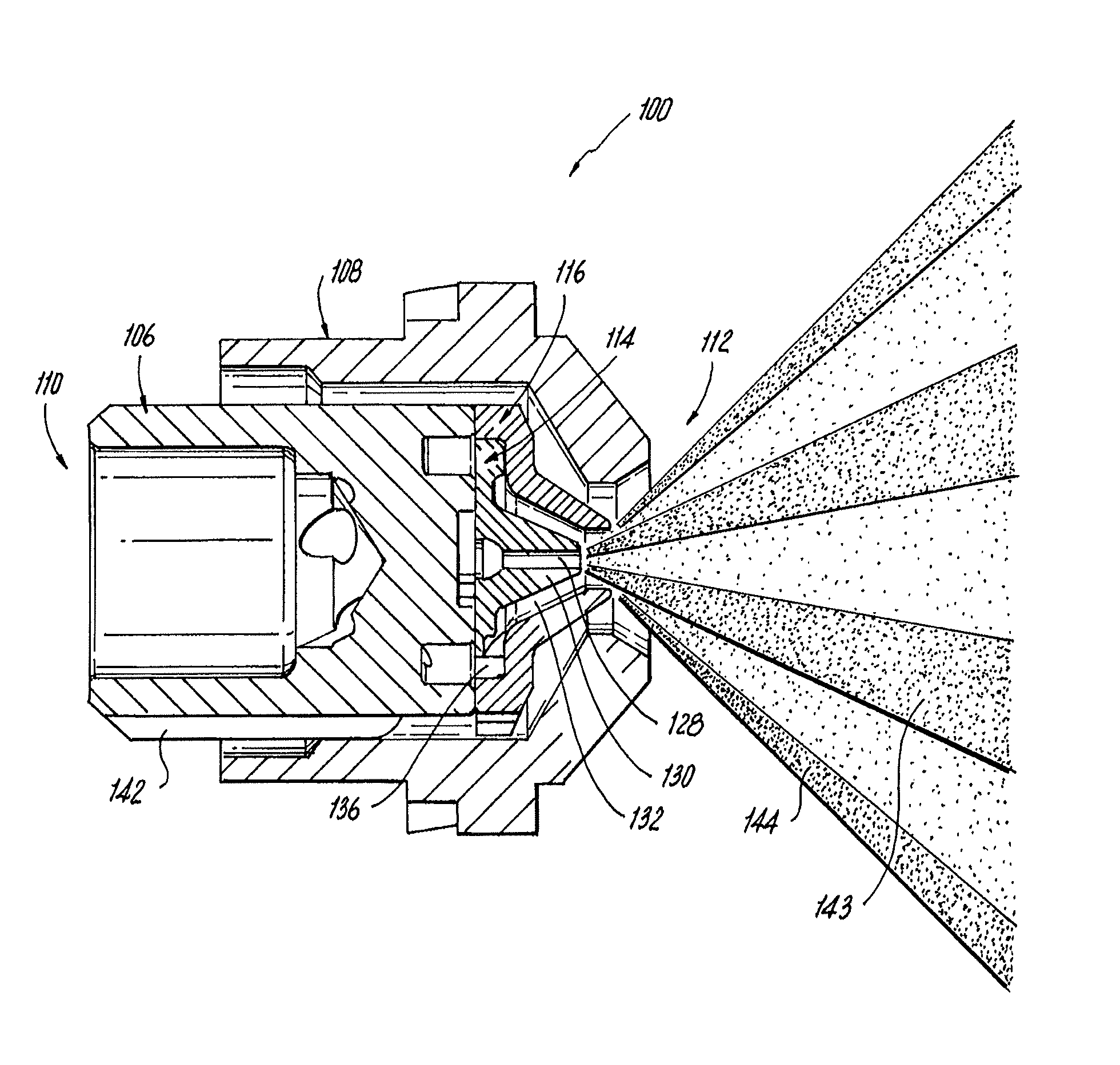
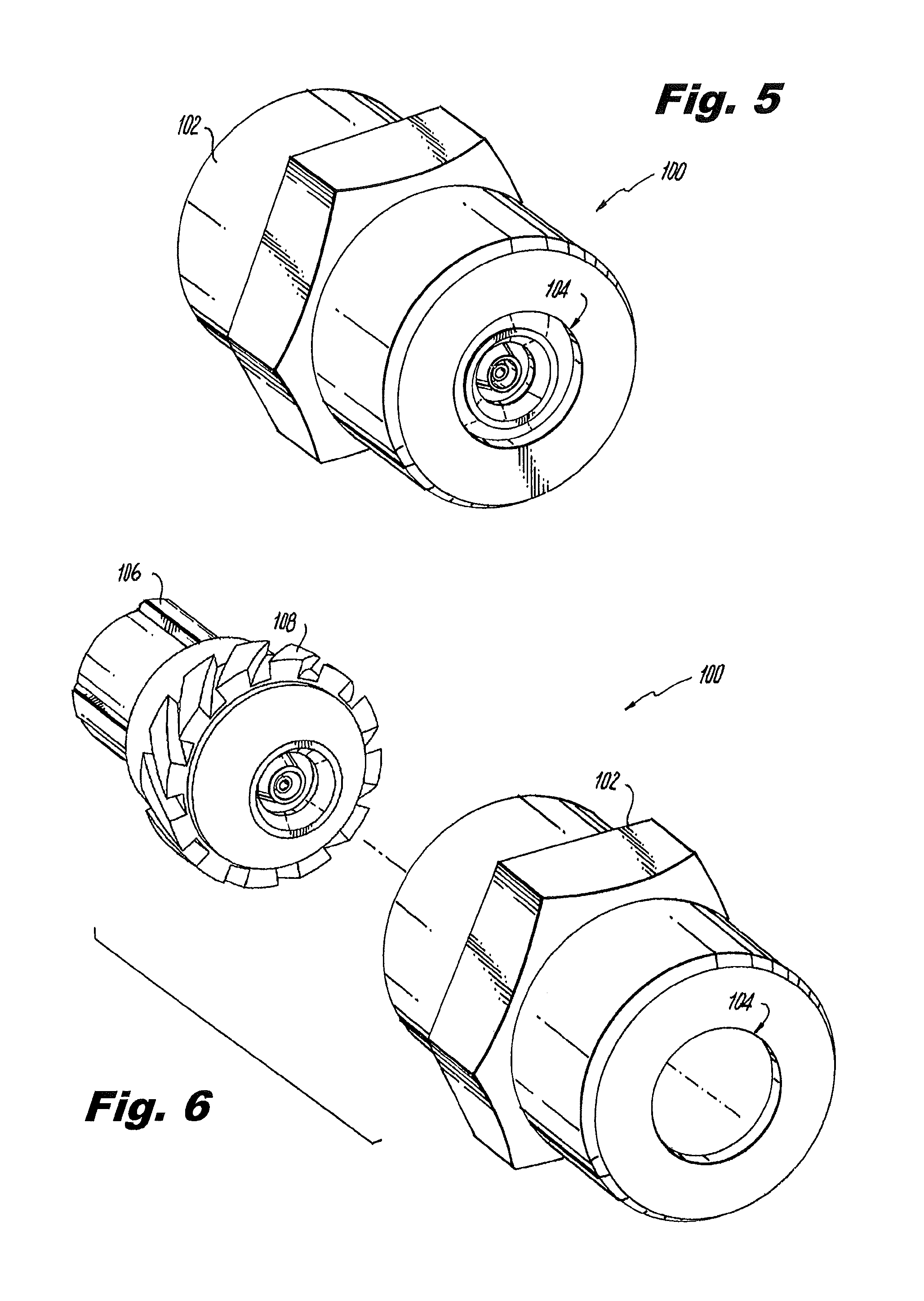
[0036]Reference will now be made to the drawings wherein like reference numerals identify similar structural features or aspects of the subject invention. For purposes of explanation and illustration, and not limitation, a partial view of an exemplary embodiment of an atomizer in accordance with the invention is shown in FIG. 5 and is designated generally by reference character 100. Other embodiments of atomizers in accordance with the invention, or aspects thereof, are provided in FIGS. 6-20, as will be described. The systems of the invention can be used to produce atomized sprays of liquid with a substantially solid spray cones over a range of pressures.

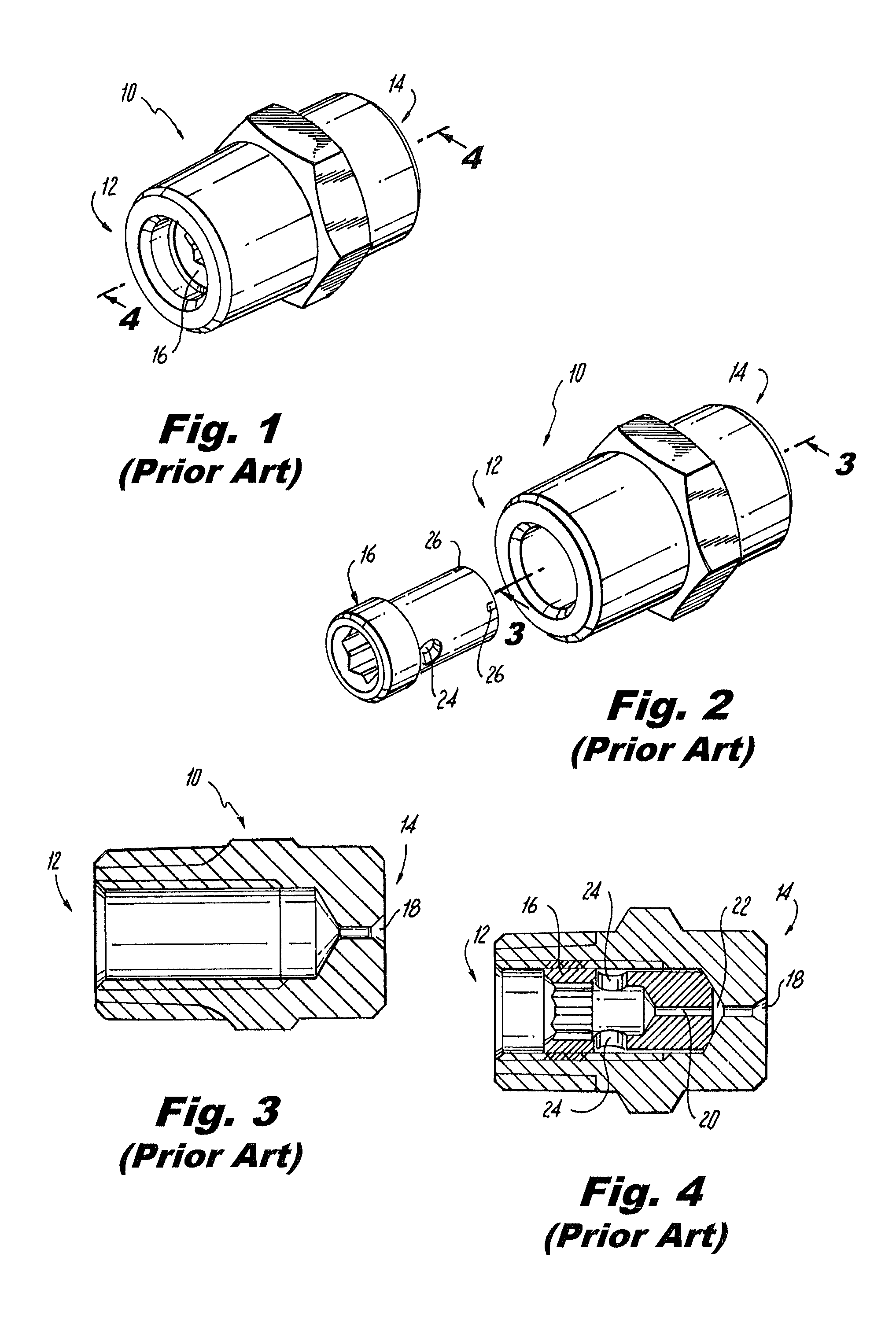
[0037]With reference first to FIG. 1, a pressure atomizer 10 of the prior art is shown having an inlet end 12 and an outlet end 14. A core 16, shown separately in FIG. 2, divides the flow internally to produce a solid spray cone. Outlet end 14 includes a single outlet orifice 18, shown in FIG. 3, which is fed from two sources. Firs...


PUM


Abstract

An atomizer includes an atomizer body having a liquid inlet and a spray outlet with a liquid flow circuit defined through the inner atomizer body for fluid communication of liquid from the inlet to the spray outlet. The liquid flow circuit branches into a plurality of sub-circuits. Each sub-circuit is configured to produce a spray cone of atomized liquid issuing from the spray outlet such that the spray cone of each sub-circuit has a different cone angle. The sub-circuits are mechanically separated from one another to limit interaction of liquid in the sub-circuits and thereby produce a distinct and stable spray cone from each sub-circuit over a range of liquid flow rates.

Description

BACKGROUND OF THE INVENTION[0001]1. Field of the Invention[0002]The present invention relates to injectors and nozzles for spaying liquids, and more particularly to pressure atomizers.[0003]2. Description of Related Art[0004]A variety of devices are known for producing a spray from a pressurized liquid. Many of these are pressure atomizers designed to atomize fuel, water, or other liquids into a fine spray of droplets. Pressure atomizers can be made relatively small and therefore lend themselves to applications where space is limited. An exemplary pressure atomizer or nozzle is described in U.S. Pat. No. 3,680,793 to Tate et al.[0005]In traditional configurations, the spray produced from a pressure atomizer has a shape that changes depending on the applied flow rate and pressure. Typically a pressure atomizer will produce a spray shape that varies from a discrete jet, to a solid cone, to a hollow cone, as the applied pressure and flow rate increase.[0006]In various applications, suc...

Claims


Application Information

Patent Timeline
Patent Type & Authority Patents(United States)
IPC IPC(8): B05B1/34
CPCB05B1/06B05B7/10B05B7/061B05B7/067B05B1/02B05B1/14
Inventor MYERS, STEVE JAY
Owner COLLINS ENGINE NOZZLES INC
Learn More