
Compact tangential tracking tonearm mechanism

a technology of tangential tracking and tonearm, which is applied in the direction of recording head arrangement, support for head, instruments, etc., can solve the problems of signal errors due to inaccurate rendering of recorded material, reduce sound fidelity,

Active Publication Date: 2013-11-05
SCHRODER FRANK
View PDF15 Cites 10 Cited by
  • Summary
  • Abstract
  • Description
  • Claims
  • Application Information

AI Technical Summary

Benefits of technology

The present invention is a tangential tracking tonearm mechanism that reduces playback distortion and tracks the original master during playback on a disk. It uses a compact subassembly with two rotary bearings and a coupling linkage to closely mimic the motion of the cutting stylus used during creation of the master. The bearing technology reduces frictional losses to minimize wear on the walls of the groove being played back and assists in maintaining accurate tangency throughout playback. The magnet technology reduces the degree of error from tangency in tracking. Overall, the invention improves the fidelity of the audio signal and enhances the overall sound quality.

Problems solved by technology

A radial tracking tonearm plays back the audio material in a way that loosely approximates the way in which the original master was created, and leads to reduced sound fidelity.
Terms commonly used to describe signal errors due to inaccurate rendering of the recorded material because the tracking during playback does not closely match the conditions under which the original master was created are “playback distortion” and “tracking distortion.”

Method used


Image

  • Compact tangential tracking tonearm mechanism
  • Compact tangential tracking tonearm mechanism
  • Compact tangential tracking tonearm mechanism

Examples


Embodiment Construction

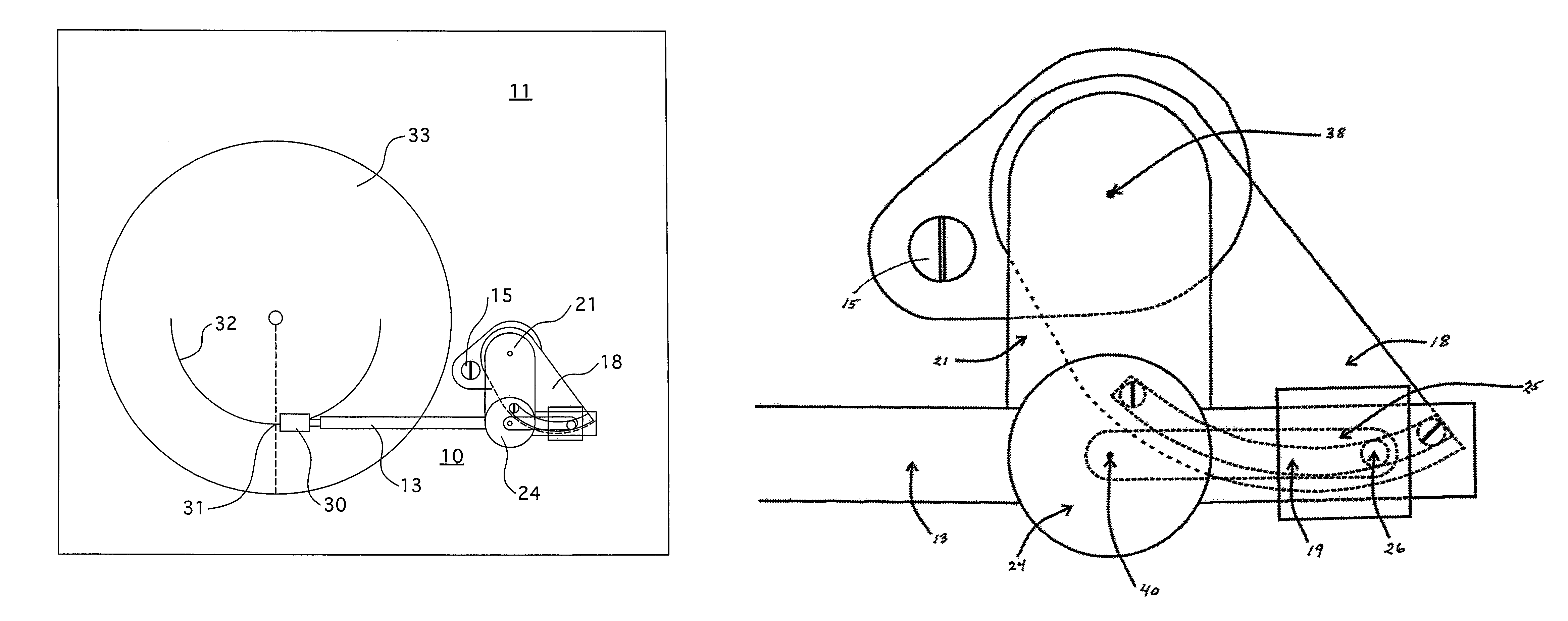
[0023]Referring now to the drawings, the invention is shown in FIGS. 1 through 6 as a set of components of a tonearm mechanism 10 assembled atop a planar surface of a phonograph turntable. In FIG. 1, attached above turntable surface 11 is tonearm bearing subassembly 12, which in turn supports tonearm 13. A component of tonearm bearing subassembly 12, shown in FIG. 3, is tonearm mounting collar 14 which is affixed, via base screw 15 to turntable surface 11. Supported by tonearm mounting collar 14 is a vertically-oriented base bearing subassembly 16. Referring to FIG. 3, attached or incorporated within base bearing subassembly 16 are vertical bearing housing 17, base bearing 34, guide platform 18 and magnet guide 19, and base shaft 20.

[0024]Referring again to FIG. 3, attached to the top of base shaft 20 is swivel platform 21. Inserted in a hole in swivel platform 21 and rigidly affixed is vertically-oriented tonearm bearing-housing 22, containing upper swivel bearing 35 and lower swiv...


PUM

PropertyMeasurementUnit
diameteraaaaaaaaaa
heightaaaaaaaaaa
heightaaaaaaaaaa

Abstract

The invention relates to tonearm tracking mechanisms in phonograph players and mechanical devices constructed for the purpose of reproducing or playing back recorded audio material previously impressed, in the form or grooves, onto a surface of a disk, which are commonly called phonograph players or turntables. Such disk is commonly called, among other similar words, a phonograph record or a vinyl disk. The present invention is a tangential tracking tonearm mechanism, wherein the tonearm bearing subassembly has two rotary bearings in the lateral plane and a coupling linkage built into a compact subassembly. The collective contribution of these elements, when properly configured and appropriately adjusted, make, during playback of audio material on a disk, reduced playback distortion over radial tracking mechanisms and closely mimics the conditions under which nearly all masters are made.

Description

BACKGROUND OF THE INVENTION[0001]The present invention relates to tonearm tracking mechanisms in phonograph players. More particularly, the present invention relates to mechanical devices constructed for the purpose of reproducing or playing back recorded audio material previously impressed, in the form or grooves, onto a surface of a disk. Such devices are commonly called phonograph players or turntables. Such disk is commonly called, among other similar words, a phonograph record or a vinyl disk. Even more particularly, the present invention describes a novel design of the tonearm mechanism, a component part of a phonograph player which is capable of tracking a groove in a phonographic disk in a controlled fashion, most especially in a tangential manner.[0002]Conventional tonearm mechanisms fall generally into two categories: 1) a radial tracking mechanism wherein the path of a stylus, which is attached via several subcomponents to the end of one end of a tonearm, follows a curved...

Claims


Application Information

Patent Timeline
Patent Type & Authority Patents(United States)
IPC IPC(8): G11B3/10
CPCG11B3/10G11B3/34G11B3/12
Inventor SCHRODER, FRANK
Owner SCHRODER FRANK
Learn More