
Radiation shield device and associated method

a radiation shield and shielding technology, applied in the field of active radiation shield devices, can solve the problems of human cells being damaged by radiation exposure, affecting the use of radiation absorbing materials, and limiting the magnetic field generated, so as to achieve the effect of deflecting charged particles and limiting the generated magnetic field

Active Publication Date: 2013-11-05
THE BOEING CO
View PDF13 Cites 11 Cited by
  • Summary
  • Abstract
  • Description
  • Claims
  • Application Information

AI Technical Summary

Benefits of technology

The patent describes a device and method for shielding an area from radiation. The device includes a first shell with coils that encircle the area to be shielded and a second shell with coils that surround the first shell. The coils of the first shell and second shell are arranged in pairs and in opposite directions, which reduces the magnetic field generated within the area to be shielded. The device effectively deflects charged particles released during CMEs while consuming less energy than previous methods.

Problems solved by technology

Such proton and heavy ion radiation can cause cell damage to humans exposed to such radiation.
Additionally, sensitive electronic components and other devices may be adversely affected by such radiation.
However, because of the significant amount of weight such a housing would require, the use of radiation absorbing material is not practical for space exploration and other applications.
Additionally, the absorption of high energy particles may release a different form of radiation such as gamma rays and X-rays that pass through the shielding material and create other difficulties for the crew and / or equipment.
Because of the need to minimize the weight and energy consumption of spacecrafts, systems for deflecting the radiation, for even a relatively brief period of time, such as a day or two, have not been practical based upon the amount of material and / or energy required for such systems.

Method used


Image

  • Radiation shield device and associated method
  • Radiation shield device and associated method
  • Radiation shield device and associated method

Examples


Embodiment Construction

[0020]Embodiments of the present disclosure now will be described more fully hereinafter with reference to the accompanying drawings, in which some, but not all embodiments are shown. Indeed, these embodiments may be embodied in many different forms and should not be construed as limited to the embodiments set forth herein; rather, these embodiments are provided so that this disclosure will satisfy applicable legal requirements. Like numbers refer to like elements throughout.

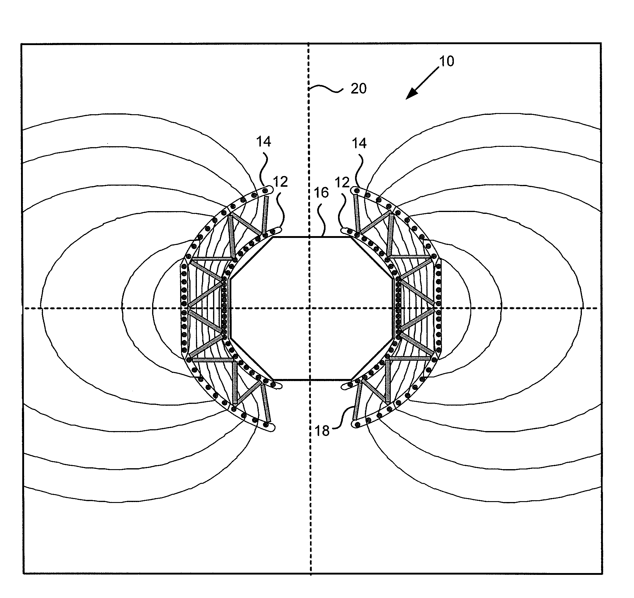
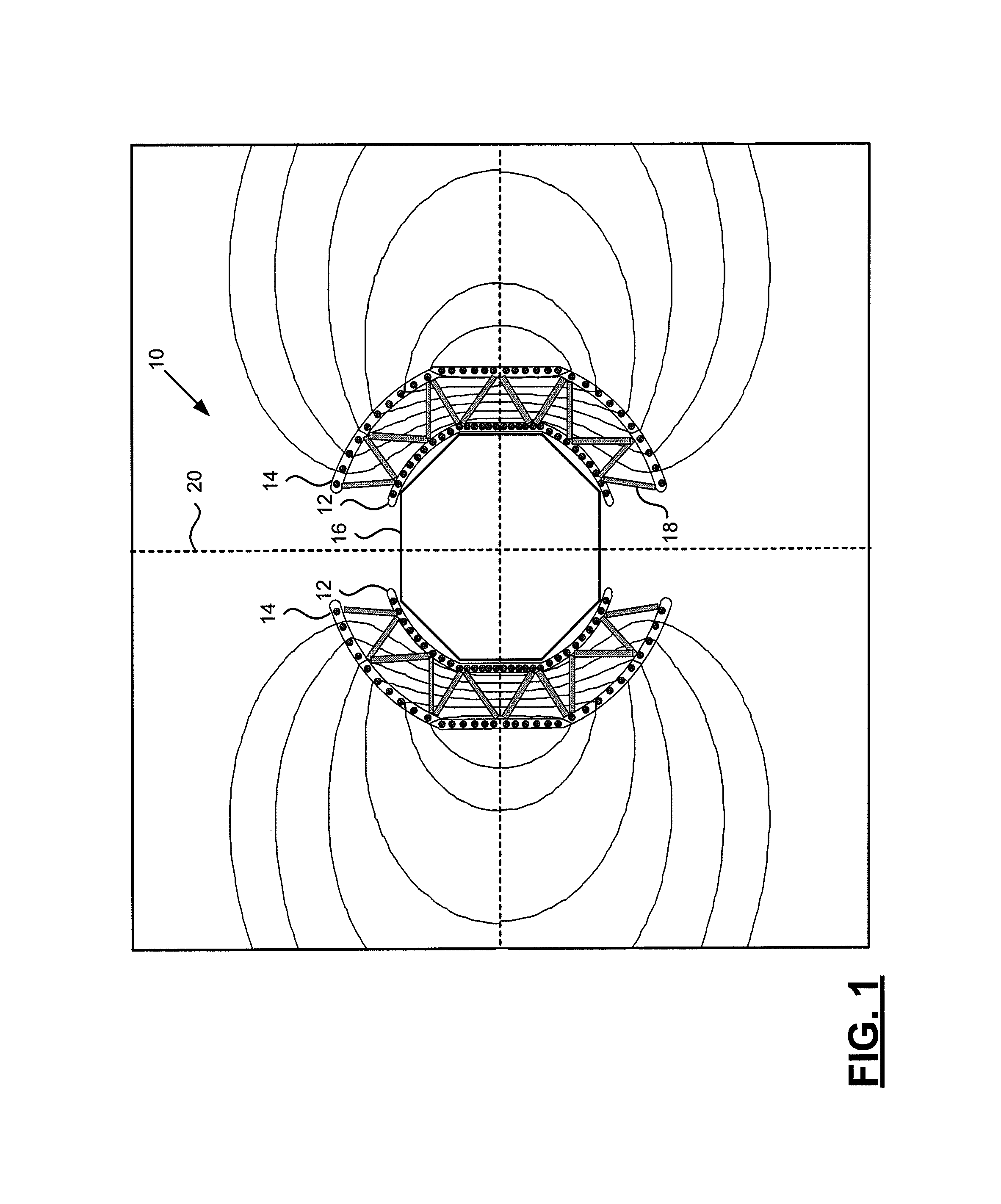
[0021]Referring now to FIG. 1, the radiation shield device 10 in accordance with one embodiment of the present disclosure is illustrated. The radiation shield device 10 is generally described herein as providing protection from radiation for a manned space vehicle or a habitat for celestial bodies, particularly during CME events. However, further embodiments of the present disclosure may include radiation shield devices for any situation in which protection from particle radiation is desired beyond the earth's m...


PUM


Abstract

A method and device of shielding an area from radiation are provided. A radiation shield device may include first and second shells at least partially surrounding the area with the second shell being spaced apart from and further away from the area than the first shell. Both the first and second shells include a plurality of coils that are arranged in paired coil groupings and that encircle the area to be shielded from radiation. The coil groupings of the first shell may be configured to support current flow in an opposite direction to that in which the paired coil groupings of the second shell are configured to support current flow. As such, each coil grouping of the first shell has north and south poles that are correspondingly oppositely positioned from the north and south poles of the paired coil grouping of the second shell.

Description

TECHNOLOGICAL FIELD[0001]Embodiments of the present disclosure relate generally to methods and devices for shielding an area from radiation and, more particularly, to an active radiation shield device and an associated method.BACKGROUND[0002]The sun occasionally releases significant amounts of charged particles during events known as coronal mass ejectas (“CMEs”). The charged particles released during CMEs include electrons, protons, and heavy ions. Each CME may last for about one or two days in the vicinity of earth, but their effects may linger for up to a week. Such proton and heavy ion radiation can cause cell damage to humans exposed to such radiation. Additionally, sensitive electronic components and other devices may be adversely affected by such radiation. Therefore, even though CMEs are relatively uncommon occurrences, the amounts of radiation they could potentially inflict upon a crew and equipment of a spacecraft suggests that consideration be given to shielding part or a...

Claims


Application Information

Patent Timeline
IPC IPC(8): B64G1/54
CPCB64G1/54G21F1/00G21F3/00
Inventor KINSTLER, GARY A.
Owner THE BOEING CO
Learn More