
Transversal load insensitive optical waveguide, and optical sensor comprising a wave guide

a technology of optical sensors and waveguides, which is applied in the direction of force measurement by measuring optical property variation, cladded optical fibres, instruments, etc., can solve the problems of distortion of reflection wavelength characteristics, limit the application field of such fibers for accurate measurement, etc., and achieve limited optical characteristics and limited optical characteristics for measuring strain.

Active Publication Date: 2015-02-05
NEDERLANDSE ORG VOOR TOEGEPAST-NATUURWETENSCHAPPELIJK ONDERZOEK (TNO)
View PDF6 Cites 1 Cited by
  • Summary
  • Abstract
  • Description
  • Claims
  • Application Information

AI Technical Summary

Benefits of technology

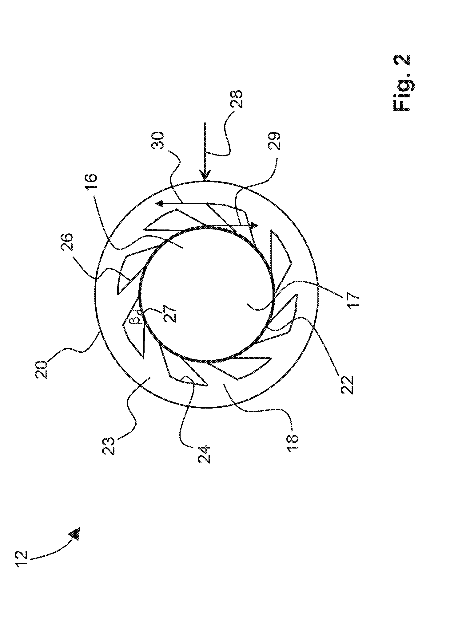
The present invention provides an optical wave guide with a cladding structure that can deflect radial loads on the exterior surface of the wave guide in a way that prevents deformation of the core and maintains optical characteristics. This is achieved by a mechanical connection between the exterior surface and the primary section surface that for each point on the exterior surface and the corresponding point on the primary section surface, a direct radial connection between these two points is absent for at least a part of the distance between them. This results in a wave guide that is insensitive to any radial load and can be used for optical sensors based on measuring deviations in optical characteristics. The invention also provides a specific embodiment wherein the cladding structure consists of two ribs that transfer forces to each other, resulting in only a deformation of the outer cladding and minimal deformation of the primary section.

Problems solved by technology

This limits the field of application of such fibers for accurate measurement of longitudinal strain, since situations wherein an unequal distribution of pressure over the length of the fiber are to be avoided.
Because for a FBG, this will lead to unequal change in the local period of the grating and causes distortion in the reflection wavelength characteristic.

Method used


Image

  • Transversal load insensitive optical waveguide, and optical sensor comprising a wave guide
  • Transversal load insensitive optical waveguide, and optical sensor comprising a wave guide
  • Transversal load insensitive optical waveguide, and optical sensor comprising a wave guide

Examples


Embodiment Construction

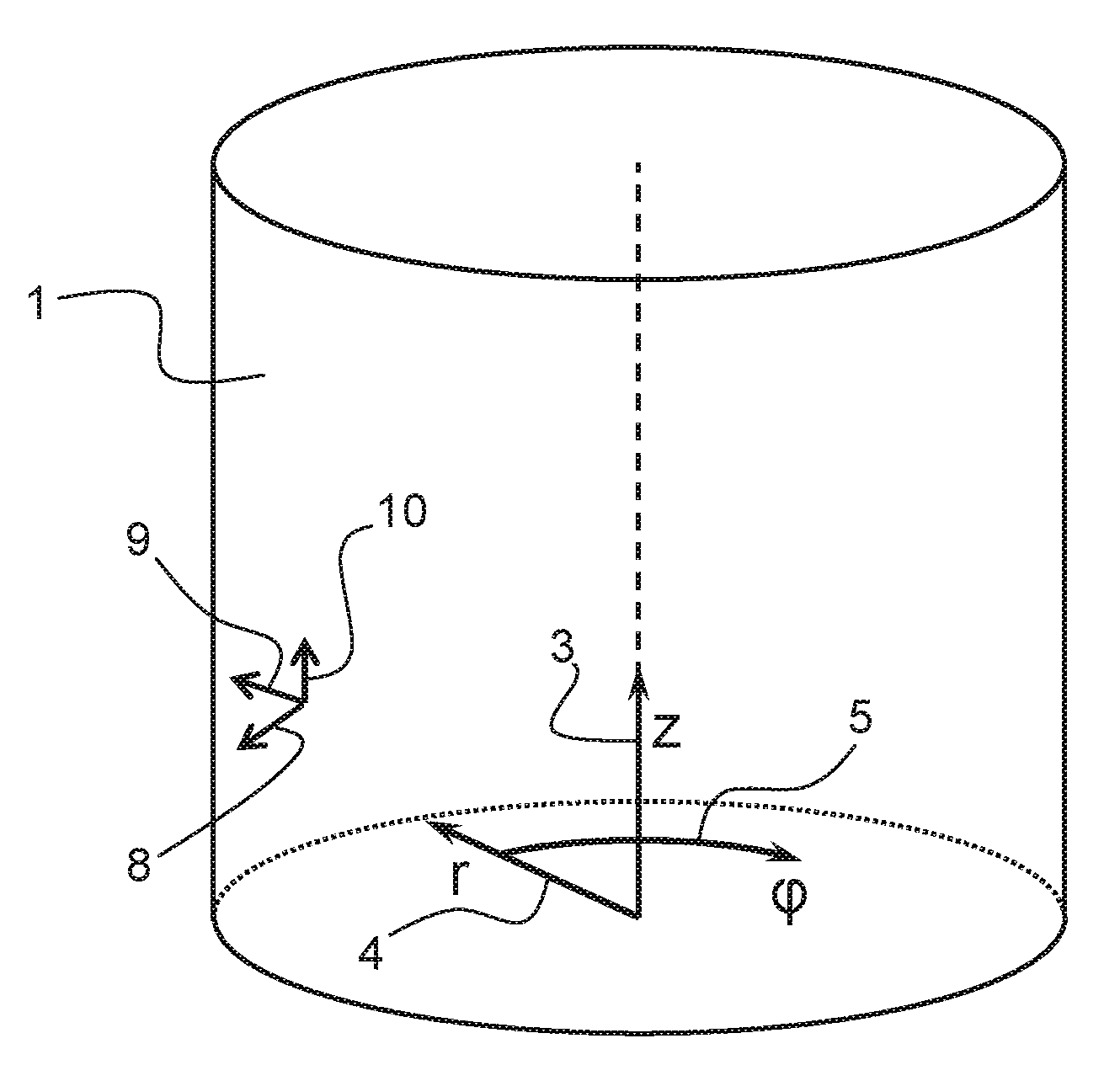
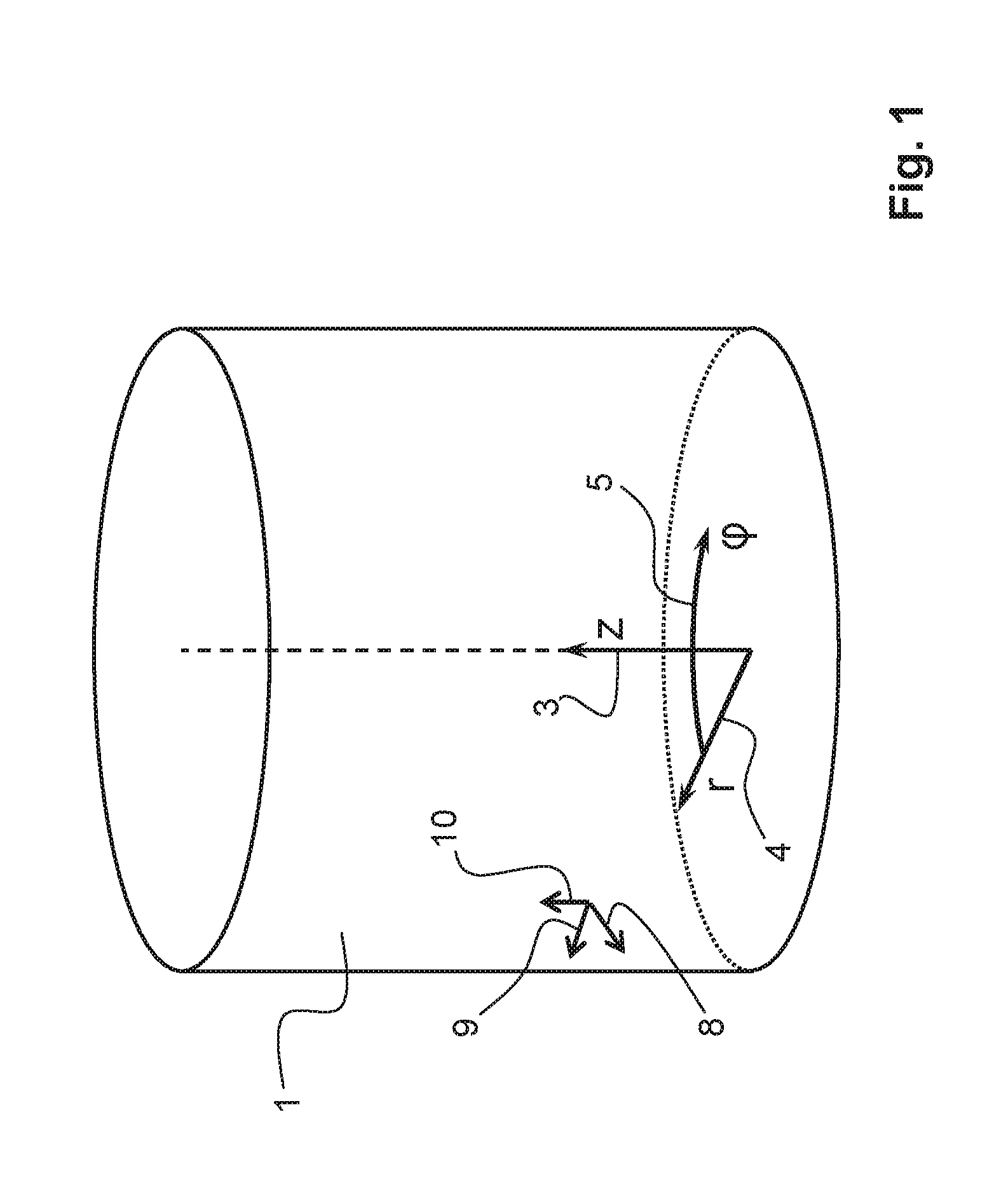
[0031]For illustrated and explanatory purposes only, FIG. 1 schematically illustrates a cylindrical coordinate system known to the skilled person, and as used for defining specifics of the present invention.

[0032]The cylindrical coordinate system is schematically illustrated by the axial / longitudinal axis 3, geometrically denoted with coordinate parameter z, and the radial axis 4 geometrically related to coordinate parameter r. The circular axis 5 defines the angular position geometrically indicated by coordinate parameter φ. Any point on a cylinder 1 may be defined by means of its coordinates (z, r, φ) defining respectively the axial position, the radial position, and the angular position on the cylinder 1. As known to the skilled person, the cylindrical coordinate system is in particular useful for defining three dimensional geometrical structures, comprising a rotational symmetry about a longitudinal axis (z). In FIG. 1, the cylinder 1 illustrated and defined by its surface 1 als...


PUM

PropertyMeasurementUnit
distanceaaaaaaaaaa
tangential forceaaaaaaaaaa
angleaaaaaaaaaa

Abstract

A transversal load insensitive optical waveguide includes a primary section having a core. The waveguide may further include an outer cladding. The primary section includes a primary section surface and the outer cladding includes an exterior surface mechanically attached to the primary section surface by an interior cladding structure forming a mechanical connection. The cladding structure is such that for at least part of a distance between each two radial corresponding points on the exterior surface and the primary section surface respectively, the mechanical connection deviates from being radial, so that a radially-directed load on an exterior surface of the outer cladding is deflected by the cladding structure.

Description

FIELD OF THE INVENTION[0001]Transversal load insensitive optical waveguide, said waveguide comprising a primary section comprising a core, and said waveguide further comprising an outer cladding, wherein said primary section comprises a primary section surface and said outer cladding comprises an exterior surface. In addition, the present invention is directed to an optical sensor for measuring strain, comprising a wave guide as described above.[0002]An important and major field of application of optical wave guides such as optical fibers, is the field of optical sensors for sensing a large variety of physical parameters. These parameters include strain, force, torque, displacement, vibration, temperature, and many others. In fiber based sensors, the parameters to be determined are being measured based on optical characteristics of the fiber used. These optical characteristics are for example dependent on the amount of strain applied to the fiber, enabling use of such a fiber in an ...

Claims


Application Information

Patent Timeline
Patent Type & Authority Applications(United States)
IPC IPC(8): G02B6/036G01L1/24G02B6/34
CPCG02B6/036G01L1/246G02B6/34G02B6/021G02B6/02171G02B6/02357G02B6/02361G02B6/02366G02B6/02371G02B6/03694
Inventor CHENG, LUN KAITOET, PETER MARTIJN
Owner NEDERLANDSE ORG VOOR TOEGEPAST-NATUURWETENSCHAPPELIJK ONDERZOEK (TNO)
Learn More