
Hysteroscopic tissue removal system with improved fluid management and/or monitoring capabilities

a tissue removal and hysterectomy technology, applied in the field of hysterectomy tissue removal systems, can solve the problems of reproductive dysfunction, ineffective current pharmacological therapies, menorrhagia (prolonged or heavy menstrual bleeding), etc., and achieve the effect of improving fluid management and/or monitoring and being easily viewabl

Active Publication Date: 2013-10-29
HOLOGIC INC
View PDF16 Cites 39 Cited by
  • Summary
  • Abstract
  • Description
  • Claims
  • Application Information

AI Technical Summary

Benefits of technology

This solution enhances fluid management and monitoring capabilities, reducing the risk of blood leakage and maintaining stable visualization, thereby improving the efficiency and safety of the procedure.

Problems solved by technology

In many instances, uterine fibroids can grow to be several centimeters in diameter and may cause symptoms like menorrhagia (prolonged or heavy menstrual bleeding), pelvic pressure or pain, and reproductive dysfunction.
However, current pharmacological therapies are largely ineffective and merely palliative.
However, despite their widespread use, hysterectomies also possess certain disadvantages, such as a loss of fertility, sexual dysfunction, and the risks commonly associated with a major surgical procedure, such as hemorrhaging, lesions, infections, pain and prolonged recovery.
Small particles are then injected from the catheter into the fibroid artery, blocking its blood supply and causing it to eventually shrink and die.
Although this procedure is less invasive than a hysterectomy, it often results in pain-related, post-surgical complications.
Moreover, the physicians that are trained to perform uterine artery embolization are typically interventional radiologists, as opposed to physicians trained specifically to take care of gynecological problems, whereas the physicians trained specifically to take care of gynecological problems typically do not possess the skill to perform catheter-based uterine artery embolization.
When arterial blood flows or oozes into the cavity, it mixes with the distension fluid and renders visualization more difficult and, if not constrained, the flowing or oozing blood will force the suspension of the procedure.
Because the distending fluid is administered under pressure, which pressure may be as great as 100 mm Hg or greater, there is a risk, especially when vascular tissue is cut, that the distending fluid may be taken up by a blood vessel in the uterus, i.e., intravasation, which uptake may be harmful to the patient.
One shortcoming that has been noted by the present inventors in connection with existing hysteroscopic tissue removal systems, particularly of the electromechanical cutter variety, is that it is often difficult to maintain fluid distension of the uterus during the resection procedure.
While most systems typically have a pressure sensor that actuates a pump to deliver replacement distending fluid to the uterus when the fluid pressure in the uterus drops due to the loss of distending fluid, the drop in pressure may be precipitous, particularly if a high suction pressure is applied.
A steep drop in uterine fluid pressure will result in the leakage of blood into the uterine cavity, causing a loss of visualization and ultimately stoppage of the procedure if the surgeon can no longer properly visualize the treatment site.
Moreover, depending on the extent and speed of the drop in uterine fluid pressure, there may be a significant lapse of time before the uterine fluid pressure can be restored to a desired level such that adequate visualization is possible.
Such lapses in time are clearly undesirable as they interrupt the resection procedure, as well as lengthen the overall time for the procedure and increase the risk of intravasation.

Method used


Image

  • Hysteroscopic tissue removal system with improved fluid management and/or monitoring capabilities
  • Hysteroscopic tissue removal system with improved fluid management and/or monitoring capabilities
  • Hysteroscopic tissue removal system with improved fluid management and/or monitoring capabilities

Examples


Embodiment Construction

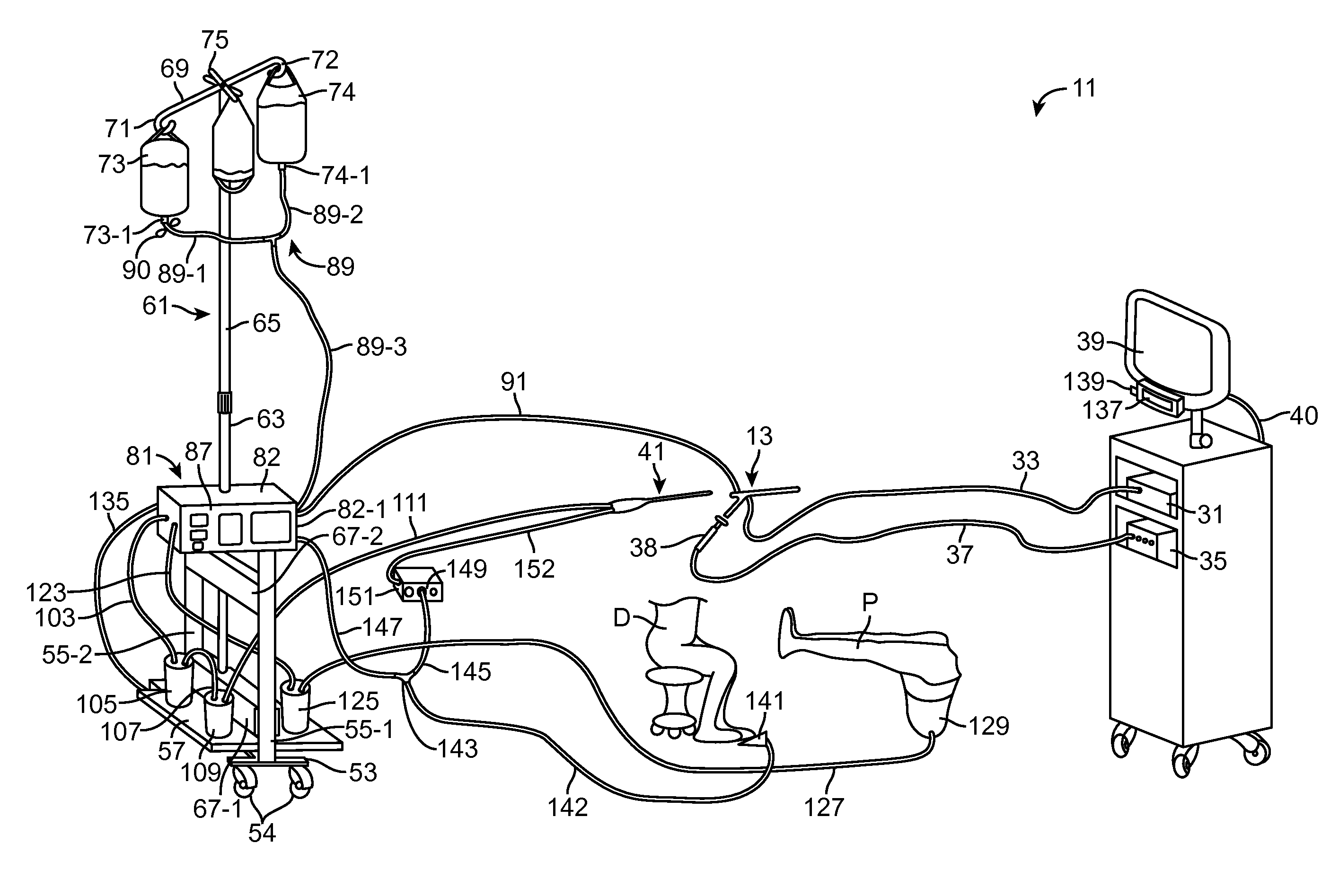
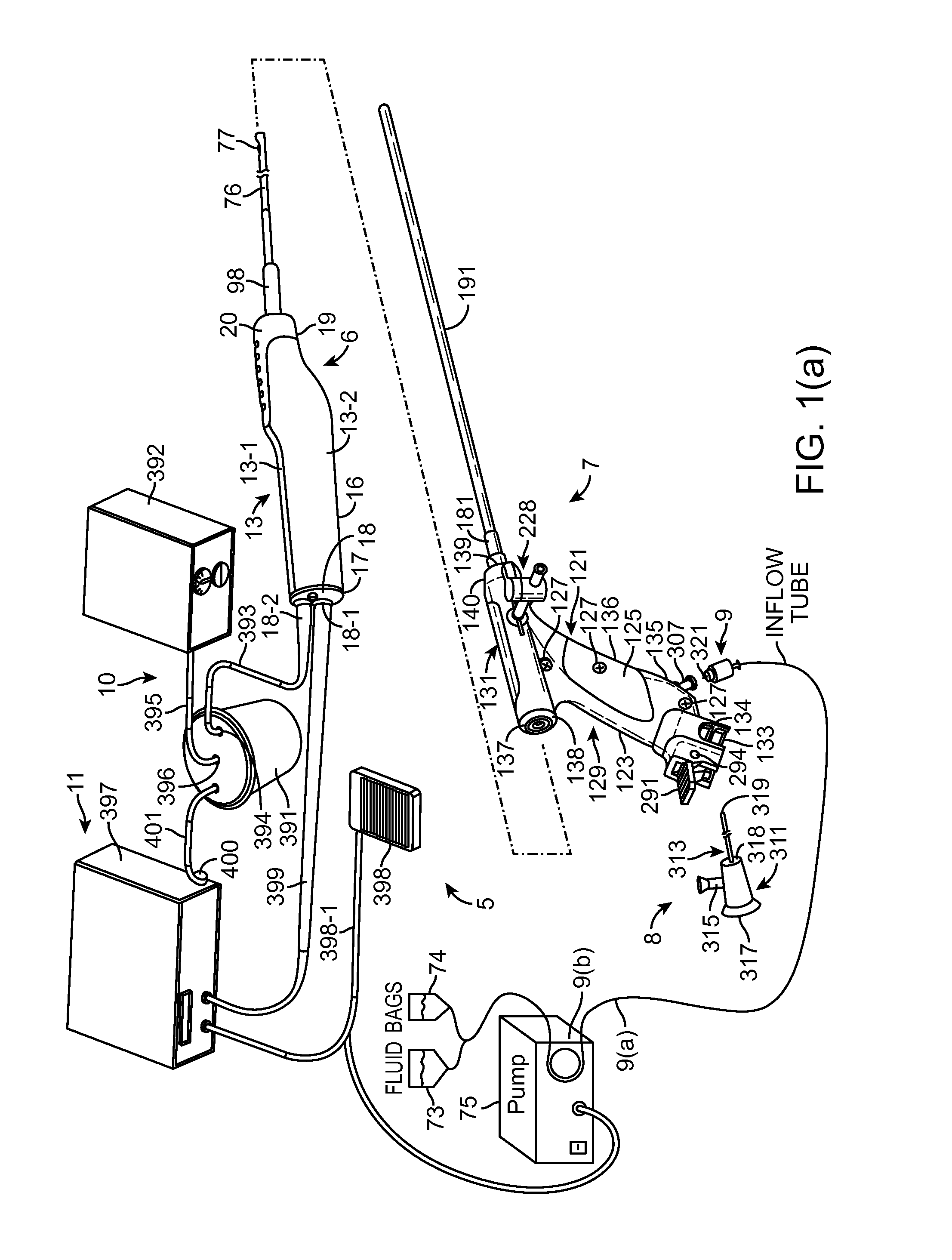
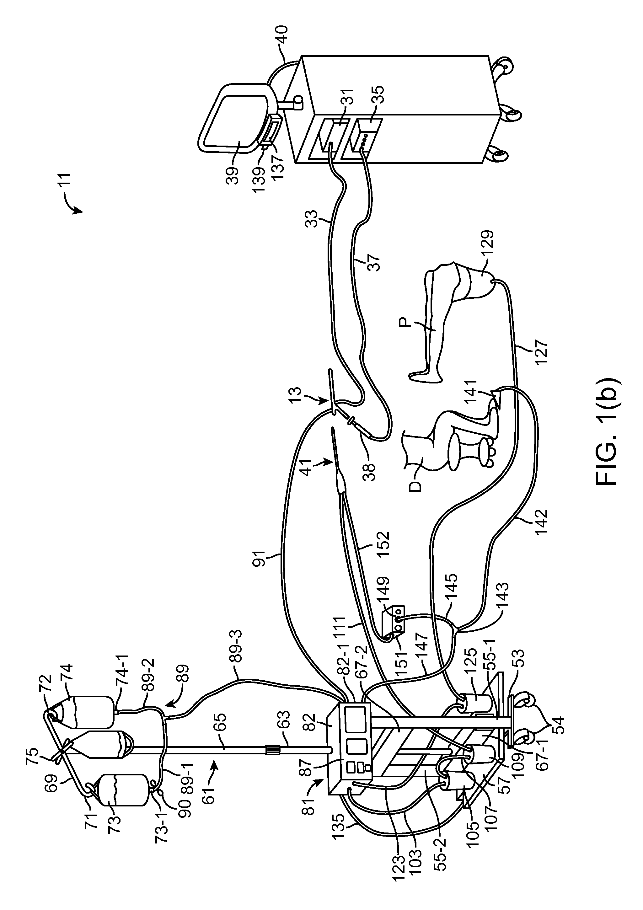
[0044]The illustrated embodiments are described below primarily in the context of devices and procedures optimized for performing one or more therapeutic or diagnostic gynecological or urological procedures such as the removal of uterine fibroids or other abnormal uterine tissue. However, it is to be understood that the illustrated and described devices and related procedures may be used in a wide variety of applications throughout the body, through a variety of access pathways.

[0045]For example, the devices of the illustrated and described embodiments may be optimized for use via open surgery, less invasive access such as laparoscopic access, or minimally invasive procedures such as via percutaneous access. In addition, the illustrated and described devices may be configured for access to a therapeutic or diagnostic site via any of the body's natural openings to accomplish access via the ears, nose, mouth, and via trans-rectal, urethral and vaginal approach.

[0046]In addition to the...


PUM


Abstract

A hysteroscopic tissue removal system having improved fluid management and / or monitoring capabilities. According to one embodiment, the system includes a hysteroscope and a tissue removal device, the tissue removal device being selectively operable and being removably mounted in an operating channel of the hysteroscope. The system also includes a fluid source and a fluid pump, the fluid pump being coupled to the fluid source and to a fluid input channel of the hysteroscope so as to pump fluid from the fluid source to the fluid input channel, the fluid pump being selectively operable. The system further includes a selectively operable switch, coupled to both the tissue removal device and the fluid pump, for actuating both the tissue removal device and the pump. If desired, a delay mechanism may be interposed between the switch and the tissue removal device to delay operation of the tissue removal device relative to the pump.

Description

RELATED APPLICATION DATA[0001]The present application claims the benefit under 35 U.S.C. §119 to U.S. provisional application No. 61 / 428,713, filed Dec. 30, 2010, the contents of which are fully incorporated herein by reference.BACKGROUND[0002]1. Field[0003]The present inventions relate generally to hysteroscopic tissue removal systems for the removal of uterine fibroids and other abnormal gynecological tissues and relate more particularly to a novel hysteroscopic tissue removal system having improved fluid management and / or monitoring capabilities.[0004]2. Description of the Related Art[0005]It is believed that uterine fibroids occur in a substantial percentage of the female population, perhaps in at least 20 to 40 percent of all women. Uterine fibroids are well-defined, non-cancerous tumors that are commonly found in the smooth muscle layer of the uterus. In many instances, uterine fibroids can grow to be several centimeters in diameter and may cause symptoms like menorrhagia (pro...

Claims


Application Information

Patent Timeline
Patent Type & Authority Patents(United States)
IPC IPC(8): A61B17/42
CPCA61B17/32002A61B17/42A61B17/320783A61B2017/00199A61B2017/0038A61B2017/320024A61B2017/320028A61B2017/320064A61B2017/320775A61B2017/4216A61B2019/464A61B2217/005A61B2217/007A61B2090/064
Inventor SHUGRUE, NICOLE MARIEADAMS, RONALD DAVID
Owner HOLOGIC INC
Learn More