
Systems and methods for projecting composite images

a composite image and image technology, applied in the field of projection displays, can solve the problems of limited resolution and light output required for large immersive screens, expensive eye shutter glasses, and the above-mentioned patents do not address the unique requirements of projecting 3d stereoscopic motion picture images, and achieve the effect of accurate overall color channel registration and high precision optics

Active Publication Date: 2013-10-29
IMAX CORP
View PDF66 Cites 31 Cited by
  • Summary
  • Abstract
  • Description
  • Claims
  • Application Information

AI Technical Summary

Benefits of technology

The present invention provides an electronic projection system that improves image fidelity by combining the output of multiple projectors by warping images to sub-pixel accuracy relative to a reference projector. This allows for higher light levels and improved image fidelity when displaying stereoscopic (3D) motion pictures or enhanced 2D motion pictures. The system uses a pixel correspondence map that is derived empirically to serve as the means for warping, which is an advantage compared to conventional systems that use analytic expressions to correct and remove distortions in all projected images. This method is also independent of the ability to model higher order distortions, making it easier to achieve sub-pixel registration.

Problems solved by technology

A disadvantage of current electronic projectors is that they are limited in resolution and light output required for large immersive screens.
As well, these patents listed above do not address the unique requirements of projecting 3D stereoscopic motion picture images.
While this approach is possible, in one implementation, it requires expensive alternate eye shutter glasses to be worn by audience members.
However, converting a system that requires images to be tiled for 2D operation and overlapped for 3D operation within a short time period time between 2D and 3D motion picture screenings would be complex and cost prohibitive.
This optimization process depends on the image being displayed and is iterative making it unsuitable for real time motion picture projection.
This negates the possibility of using off-the-shelf projectors.
In addition, there are considerable challenges involved to mechanically register pixels with a fixed sub-pixel offset and maintain this offset over repeated use.
In particular, when illuminating large screens the amount of light that must travel through the system results in thermal cycling that makes pixel registration more challenging.
The distortions result from optical or projection point differences among the projectors.
In a large cinema projection system this method of calibration is not practical.
The above patents do not address the needs that a motion picture cinema projection system must fulfill to be successful against competing display technologies.
In particular, systems that require the determination of absolute screen coordinates to superimpose images are unnecessarily complex and impractical to implement in a cinema theatre environment.
They do not take advantage of the fact that, in a theatre environment, the image from a projector has relatively low distortion and may be projected essentially without modification onto the screen.
In addition, an immersive cinematic experience requires a large field of view that can't be seen all at once.
There are additional requirements that are not easily met by existing art when the cinema projector must show both 2D and 3D presentations or when one presentation is a mixture of 2D and 3D formats.
In other cases, one must resort to using expensive shutter glasses or incur the light loss of 3D methods that use time multiplexing to distinguish left and right eye images.
Existing art does not take advantage of the different requirements of 2D and 3D presentation and the display properties required for an immersive experience.

Method used


Image

  • Systems and methods for projecting composite images
  • Systems and methods for projecting composite images
  • Systems and methods for projecting composite images

Examples


Embodiment Construction

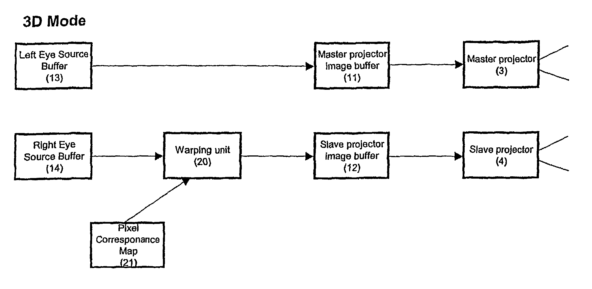
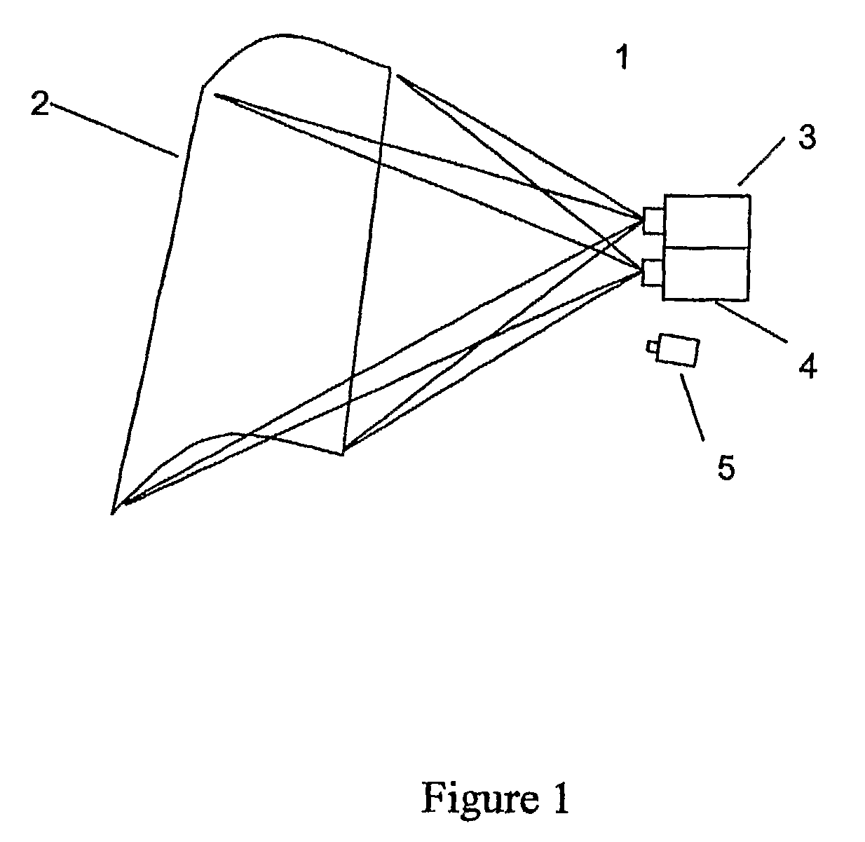
[0068]Referring to FIG. 1, a convertible projection system (1) is shown composed of two separate electronic motion picture projectors (3, 4). Other embodiments of the projection system may contain more than two electronic motion picture projectors. The projectors are not limited to a particular electronic technology and may in fact be based on DMD (deformable mirror device) technology, LC (liquid crystal) reflective or LC transmissive technology, or any other existing or emerging electronic projection technology. In FIG. 1 the two projectors (3,4) are shown in their preferred embodiment of one placed above the other; however they may also be arranged in other positions relative to one another. The two projectors, regardless of their physical arrangement, project their images onto a projection screen (2) so that they are substantially superimposed or overlapped.

[0069]In other embodiments, more than two projectors may be used. For example, more than two projectors superimposed to proj...


PUM


Abstract

Embodiments of the present invention comprise electronic projection systems and methods. One embodiment of the present invention comprises a method of creating composite images with a projection system comprising a first projector and at least a second projector, comprising generating a correspondence map of pixels for images by determining offsets between pixels from at least a second image from the second projector and corresponding pixels from a first image from the first projector, receiving a source image, warping the source image based at least in part on the correspondence map to produce a warped image, and displaying the source image by the first projector and displaying the warped image by the second projector to create a composite image.

Description

RELATED APPLICATION DATA[0001]This application is the U.S. national phase of International Application No. PCT / US2006 / 015892 filed on Apr. 26, 2006 and published in English on Nov. 2, 2006 as International Publication No. WO 2006 / 116536 A1, which application claims priority to U.S. Provisional Application No. 60 / 674,981, filed Apr. 26, 2005, which are incorporated in their entirety herein by reference.FIELD OF THE INVENTION[0002]This invention generally relates to the field of projection displays and more particularly to the field of electronic projection systems comprising two or more projectors whose output is combined to form a composite image.BACKGROUND[0003]Increasingly there is a need for motion picture producers and exhibitors to differentiate their product at motion picture theatre multiplexes from that of competitors and to differentiate the theatre experience from that which customers can obtain at home. One approach is to provide images that are larger, sharper and bright...

Claims


Application Information

Patent Timeline
Patent Type & Authority Patents(United States)
IPC IPC(8): H04N13/04G03B21/14H04N13/363
CPCH04N9/3147H04N13/0422H04N13/0425H04N13/0434H04N13/0454H04N13/0459G06T15/00G09G5/377H04N13/363H04N13/324H04N13/327H04N13/337H04N13/359H04N5/74H04N13/00
Inventor O'DOR, MATTHEWREAD, STEVENBALJET, ANTONINSULL, PHILIP
Owner IMAX CORP
Learn More