
Plasma generating apparatus and plasma processing apparatus

a technology which is applied in the field of plasma generating apparatus and plasma processing apparatus, can solve the problems of film becoming a defective product, affecting the production efficiency of plasma, and generating droplets, etc., and achieves shortening the plasma transport distance, improving the film formation rate, and high efficiency

Active Publication Date: 2013-10-22
FERROTEC
View PDF13 Cites 1 Cited by
  • Summary
  • Abstract
  • Description
  • Claims
  • Application Information

AI Technical Summary

Benefits of technology

"The present invention is about a plasma generating apparatus and a plasma processing apparatus that can remove cathode material particles (droplets) from plasma generated by a vacuum arc discharge. The droplets can cause uneven film formation and defective products when they adhere to the surface of an object to be treated. The invention solves this problem by using a magnetic filter method or a droplet collecting portion to remove the droplets from the plasma. The technical effect of this invention is to improve the quality and uniformity of plasma treatment by removing the droplets that can affect the film formation process."

Problems solved by technology

However, what becomes a problem in a surface treatment such as film formation is generation of the droplets.
When these droplets adhere to the surface of the object to be treated, the uniformity of the film formed on the surface of the object to be treated is lost, and the film becomes a defective product.

Method used


Image

  • Plasma generating apparatus and plasma processing apparatus
  • Plasma generating apparatus and plasma processing apparatus
  • Plasma generating apparatus and plasma processing apparatus

Examples


Embodiment Construction

[0157]In the following, the embodiments of the plasma generating apparatus concerning the present invention are explained in detail based on the attached drawings.

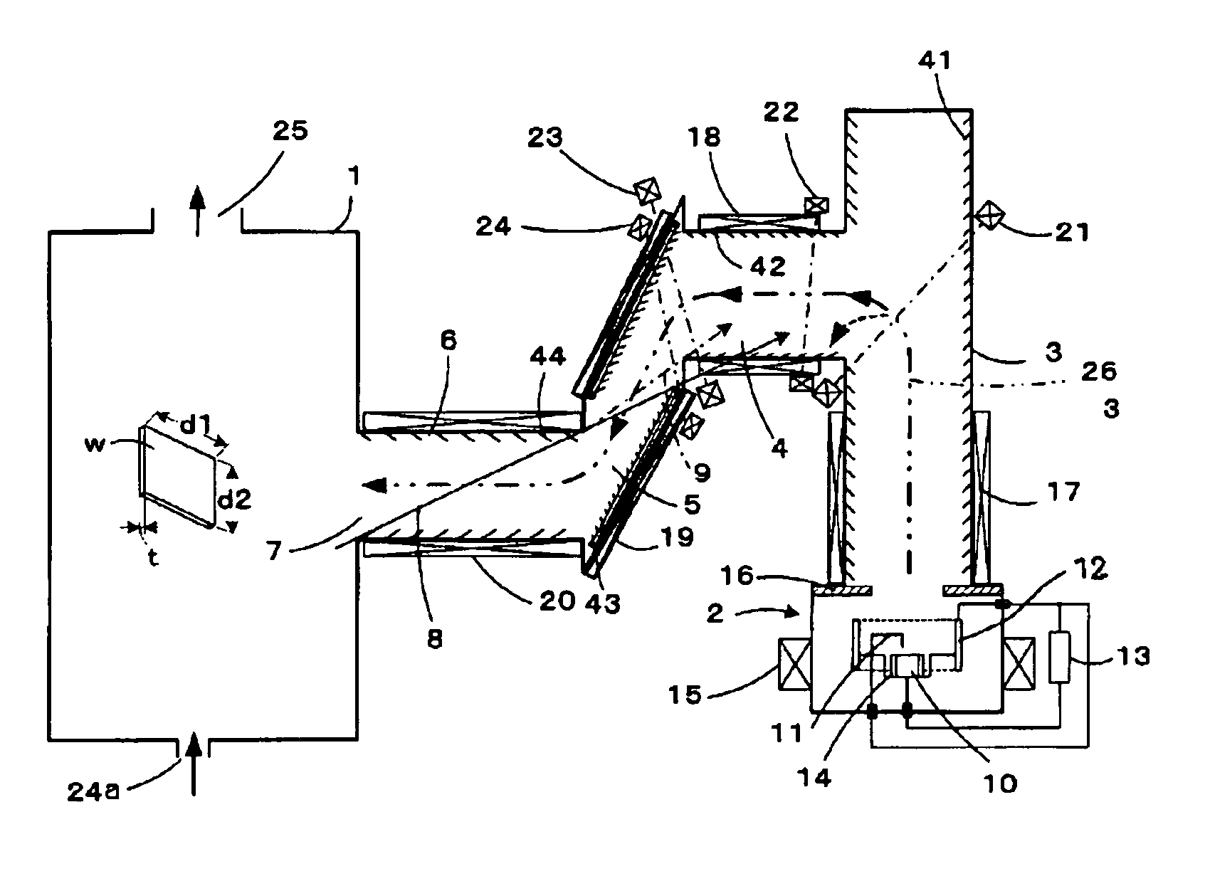
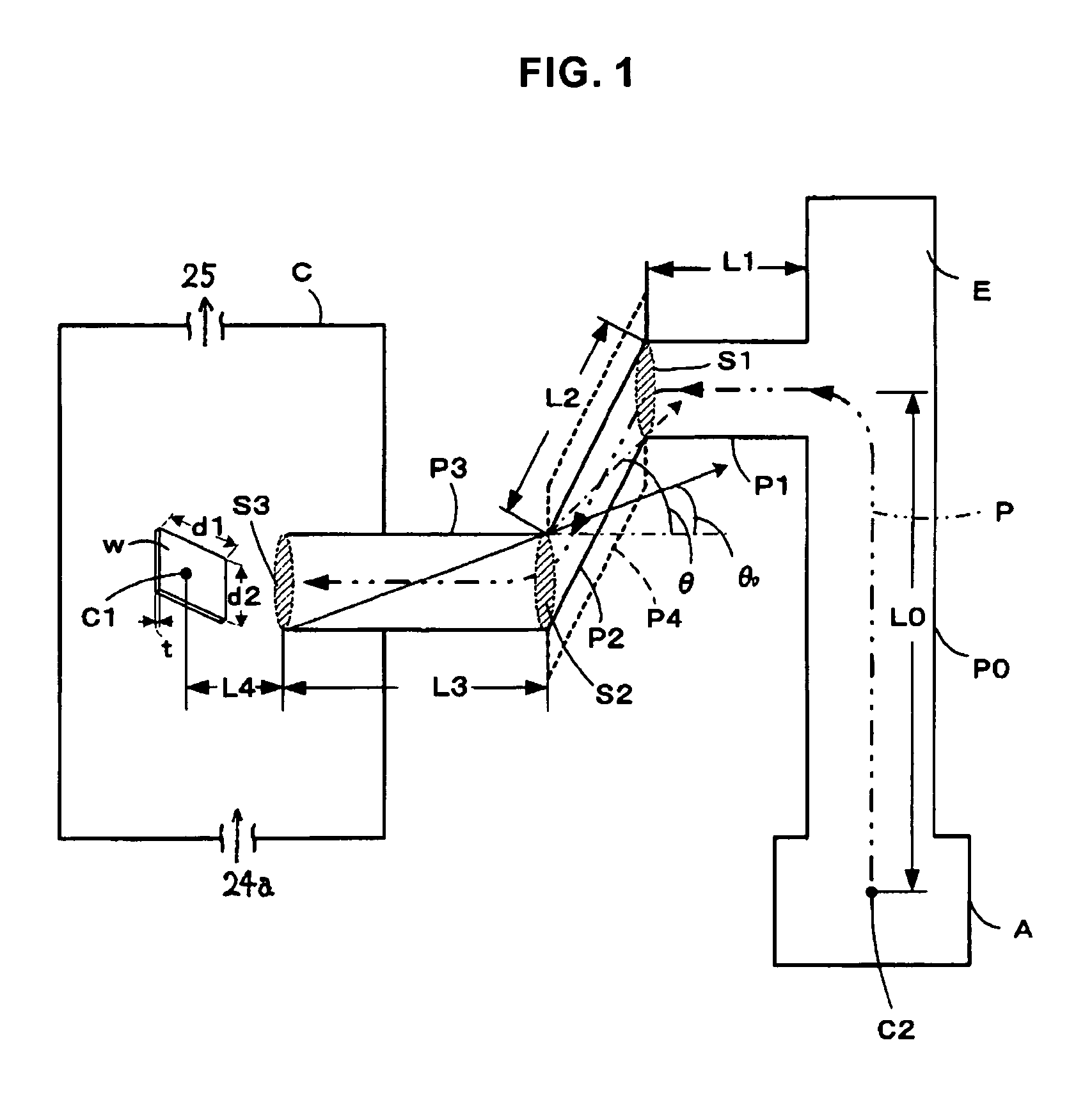
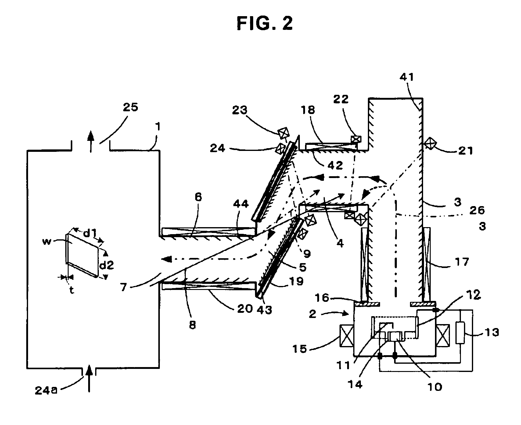
[0158]FIG. 1 is a summary configuration diagram of the plasma generating apparatus concerning the present invention. The plasma generating apparatus shown in the figure comprises plasma generating portion A that generates plasma that is supplied to plasma processing portion (chamber) C, and a plasma advancing path. Work (object to be plasma-treated) W is set up in plasma processing portion C, a reactive gas is introduced as necessary from gas inflow port 24a by a gas introduction system connected inside the chamber, and the reactant gas and the plasma stream are exhausted from exhaust port 25 by a gas exhaust system. Plasma generating portion A has a cathode (a target) in which plasma is generated by vacuum arc discharge under a vacuum environment. The plasma advancing path comprises a tube passage that circulates plasma. ...


PUM

PropertyMeasurementUnit
total lengthaaaaaaaaaa
sizeaaaaaaaaaa
sizeaaaaaaaaaa

Abstract

A plasma processing apparatus using a plasma generating apparatus by which droplets mixed in plasma can be efficiently removed and surface processing precision can be improved in film formation wherein high purity plasma is used. A droplet removing portion arranged in a plasma advancing path is composed of a straight plasma advancing tube (P0) connected to a plasma generating portion (A); a first plasma advancing tube (P1) connected to the straight plasma advancing tube (P0) in a bent manner; a second plasma advancing tube (P2) connected to a finishing end of the first plasma advancing tube (P1) by being inclinedly arranged at a predetermined inclination angle with respect to the tube axis of the first plasma advancing tube; and a third plasma advancing tube (P3), which is connected to the finishing end of the second plasma advancing tube (P2) in a bent manner and discharges plasma from a plasma outlet.

Description

FIELD OF THE INVENTION[0001]The present invention concerns with a plasma generating apparatus comprising a droplet removing section that removes cathode material particles that are produced from a cathode as a byproduct at the time of generation of plasma (henceforth referred to as “droplets”) as the plasma is generated from the target surface by a vacuum arc discharge at an arc discharge portion set under a vacuum environment, and a plasma processing apparatus for doing plasma treatment using the plasma generated by said plasma generating apparatus.BACKGROUND ART[0002]Commonly, it is known that by forming a film on the surface of a solid material in plasma or by injecting ions, the solid surface characteristics can be improved. A film formed using plasma that includes metal or nonmetal ions strengthens the abrasion / corrosion resistance of the solid surface, and it is useful as a protective film, an optical thin film, a transparent electroconductive film, or such. In particular, a c...

Claims


Application Information

Patent Timeline
Patent Type & Authority Patents(United States)
IPC IPC(8): C23C14/00H01J27/14
CPCC23C14/325C23C14/564H01J37/32357H01J37/32366H05H1/50
Inventor SHIINA, YUICHI
Owner FERROTEC
Learn More