
Method of setting an automatic level control of the plow in plowing operations of coal mining

a technology of automatic level control and mining operations, which is applied in the direction of mining structures, mine roof supports, slitting machines, etc., can solve the problems of low actual height of the face and considerable time delay, and achieve the effect of improving the quality of measurement, significantly dampening the indication of measurement value, and improving accuracy

Inactive Publication Date: 2013-10-22
RAG AG
View PDF7 Cites 8 Cited by
  • Summary
  • Abstract
  • Description
  • Claims
  • Application Information

AI Technical Summary

Benefits of technology

This patent describes a system for controlling the operation of shield support frames and pertaining boom cylinders in a longwall equipment. The system uses hydraulic cylinders to control the position of the boom and to protect the shield support frames from damage during the mining process. To prevent mechanical overstressing of the connection between the boom and the shield support frames and to improve the quality of the measurement, the control mechanisms for adjacent groups of shield support frames are balanced with each other to avoid maximum differences between the control angles. The system also uses a twin or double inclination sensor on the face conveyor for improved accuracy and a compensation circuit for dampening rotational errors caused by vibrations. Additionally, the hydraulic boom cylinders are blocked by hydraulically releasable check valves to prevent undesired changes in the control angle.

Problems solved by technology

As a consequence of the respectively existing operation conditions, the projected height is, however, not achieved in operational practice; rather, there results a lower actual height of the face, which is inventively determined when the shield support frame, which trails the plow in terms of a time delay, reaches the respective face position.
Due to the deviation between the projected height and the actual height, with continuous use of a control angle set at the boom control a face would reach the target height of the face prescribed from the standpoint of mining only with a considerable time delay.

Method used


Image

  • Method of setting an automatic level control of the plow in plowing operations of coal mining
  • Method of setting an automatic level control of the plow in plowing operations of coal mining
  • Method of setting an automatic level control of the plow in plowing operations of coal mining

Examples


Embodiment Construction

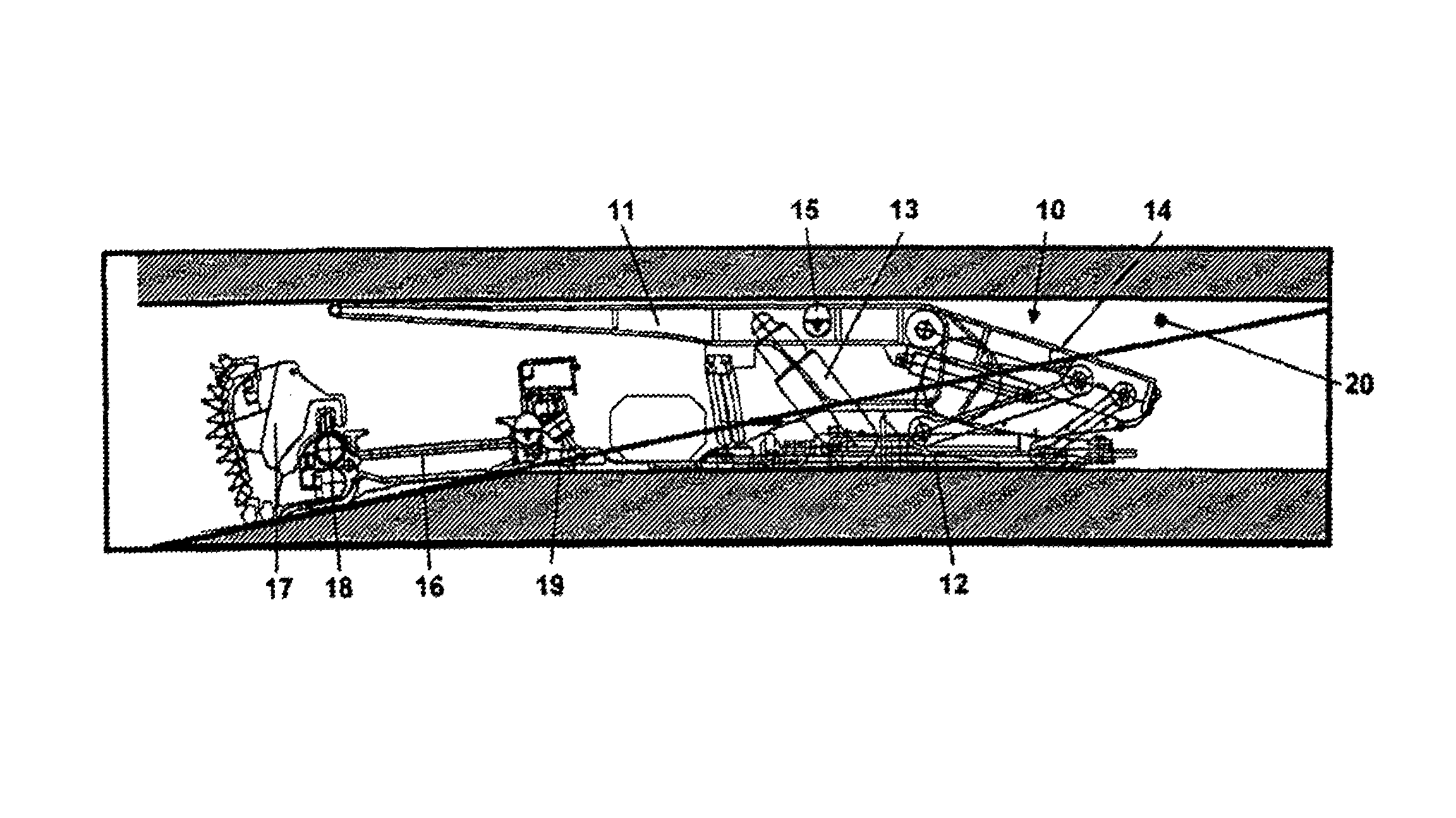
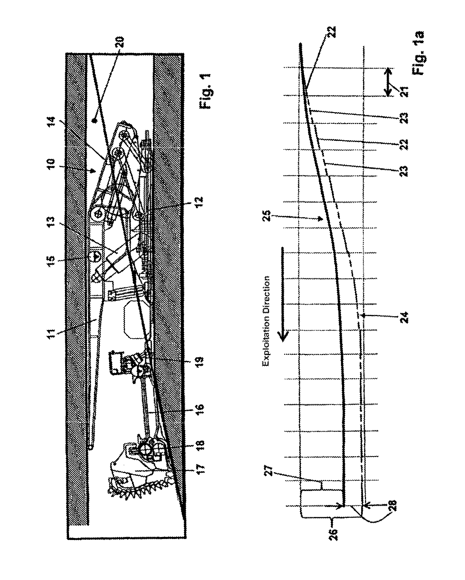
[0043]The longwall equipment schematically illustrated in FIG. 1 primarily has a shield support frame 10 with a top canopy 11 and a floor skid 12; positioned between floor skid 12 and top canopy 11 are two props 13 that are disposed parallel to one another, with only one prop being recognizable in FIG. 1. Whereas the front (left) end of the top canopy 11 protrudes in the direction of the extraction machine, linked on the rear (right) of the top canopy 11 is a gob shield 14; the construction of such a shield support frame is known, so that it will not be further explained. An inclination sensor 15 is mounted at least on its top canopy 11; as not further illustrated, on the shield support frame 10, further inclination sensors are mounted on the floor skid 12 and on the gob shield 14 and / or on the support connection rods that carry the gob shield 14. With the aid of the measured values determined by the inclination sensors, the height of the shield support frame between the top canopy ...


PUM


Abstract

A method of setting an automatic level control of a plow in longwall mining operations. By means of a boom control mechanism, a control angle for setting motion of the plow, which is guided on a face conveyor, in an exploitation direction as a climbing, plunging or neutral motion is set. For each plow stroke, a cutting depth and the control angle, derived as a differential angle between inclinations of the face conveyor and of a top canopy of a shield support frame are determined. In a calculating unit, a face height change per plow stroke is calculated therefrom and a face height, as a projected height, is associated with each face position of the face conveyor. When a shield support frame that trails behind the plow in terms of a time delay reaches a respective face position, an actual height of the face is calculated and compared with the store projected height. For subsequent plow strokes, a height differential value between the projected and actual heights, determined for a respective face position, in the sense of a self-learning effect of the calculating unit when the control angle that is to be set to achieve a projected height of the face is prescribed, is taken into consideration.

Description

BACKGROUND OF THE INVENTION[0001]The instant application should be granted the priority dates of Dec. 17, 2008, the filing date of the corresponding German patent application 10 2008 062 381.4, as well as Dec. 11, 2009, the filing date of the International patent application PCT / EP2009 / 008863.[0002]The present invention relates to a method for setting an automatic level control of the plow in longwall mining operations, in underground coal mining, equipped with a hydraulic shield support and with a face conveyor that guides the plow at a plow guide mechanism formed thereon, whereby the position of the face conveyor, including the plow guided thereon, can be changed in the exploitation direction by means of a boom control mechanism that is supported on the shield support, and, by means of the boom control mechanism, a control angle for setting the motion of the plow in the exploitation direction as a climbing motion, a dropping motion or a neutral motion can be set.[0003]One problem ...

Claims


Application Information

Patent Timeline
Patent Type & Authority Patents(United States)
IPC IPC(8): E21D23/03E21C35/24
CPCE21C35/125E21C35/24E21D23/03
Inventor JUNKER, MARTINMOZAR, ARMIN
Owner RAG AG
Learn More