Method and twin roll caster for the production of strip cast from a molten metal

a technology molten metals, which is applied in the direction of twin roll casters for the production of strip cast from molten metals, which can solve the problems of abrasive wear of insert materials wear of side plates, and abrasive wear of insert materials, so as to minimize the risk of operational disruption through molten mass solidification in the contact surface region

Inactive Publication Date: 2013-10-22
OUTOKUMPU NIROSTA
View PDF9 Cites 0 Cited by
  • Summary
  • Abstract
  • Description
  • Claims
  • Application Information

AI Technical Summary

Benefits of technology

The invention relates to a method of minimizing wear of a side plate in a casting machine. The method involves not only moving the side plate in an oscillating manner, but also changing the position of the axis of oscillation. This prevents solidification of the molten mass and reduces wear and tear on the side plate. The method is space-saving and light-weight, and can be easily incorporated into a casting machine. The invention also provides an adjustment device that facilitates the transverse movement and positioning of the side plate.

Problems solved by technology

The relative movements, necessary in the casting process, between the side plates and the front sides, of the casting rolls as well as the contact with the molten metal moving through the casting gap inevitably lead to wear of the side plate due to abrasive wear.
Thereupon abrasive wear of the insert material occurs in the region of the contact surfaces.
The heat loss in this case can be so great that molten mass solidifies on the respective positive insert.
Parasitic solidifications can cause strip defects, such as thickness discontinuities (deviation from defined tolerances), insufficient through-solidification (bulging aspects) and material tears (strip edges).
In extreme cases they may require the casting process to be aborted.
A further manifestation of the wear on the inserts of the side plates results as a consequence of strip shells forming on the cooled casting rolls during the strip casting process.
Increased material wear occurs due to the relatively high strength of these strip shells along the casting roll arc of contact.
This material wear leads to the formation of a gap between the particular casting roll and the insert associated with it, whose width (growth and swarming of the strip shell) and depth (erosion=casting material strength and / or corrosion=casting material analytics) increase starting from the level of the molten mass cast into the casting gap towards the narrowest roll distance.
Such longitudinal tearing may also require the casting to be aborted.
Common to the known possibilities of minimising wear by oscillation, however, is the disadvantage that in the case of rotational oscillation the fulcrum of the oscillation cannot be shifted or, in the case of horizontal oscillation of this movement, no rotational movement can be superimposed.
A further disadvantage of the rotation about a certain central axis, used in the state of the art described above, is that lowering of the inserts is only possible to a limited extent, since here the fulcrum is shifted in or against the casting direction.

Method used


Image

  • Method and twin roll caster for the production of strip cast from a molten metal
  • Method and twin roll caster for the production of strip cast from a molten metal
  • Method and twin roll caster for the production of strip cast from a molten metal

Examples


Embodiment Construction

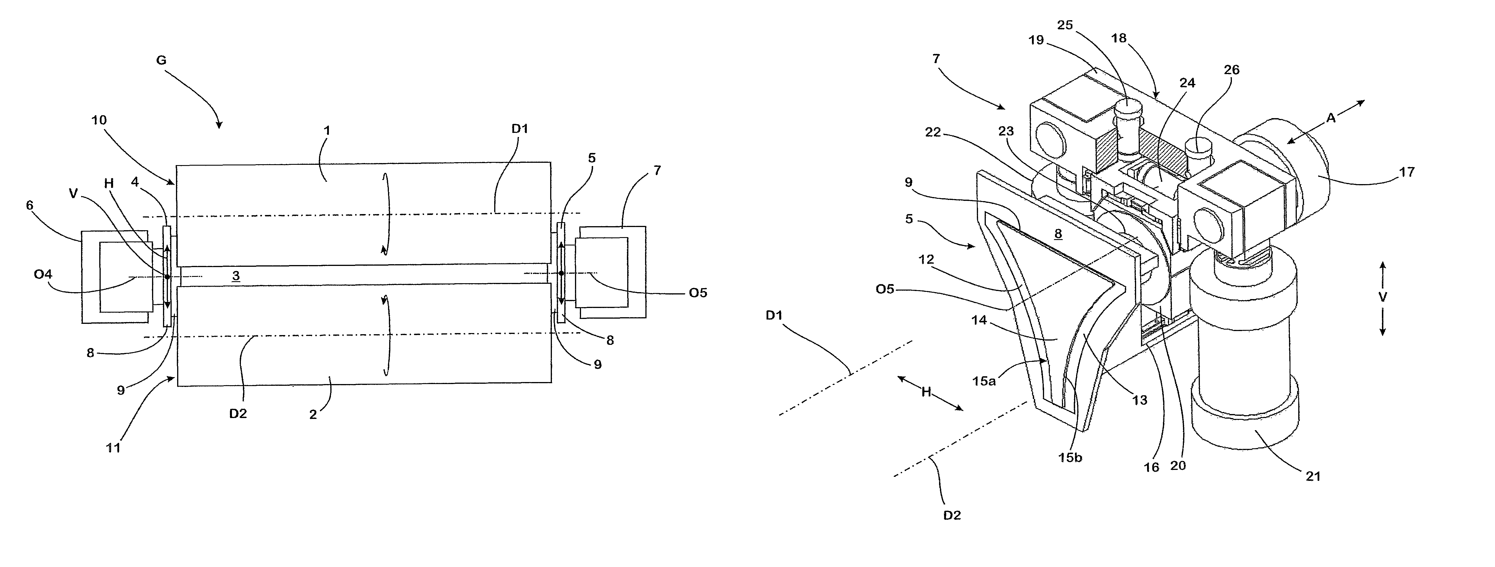
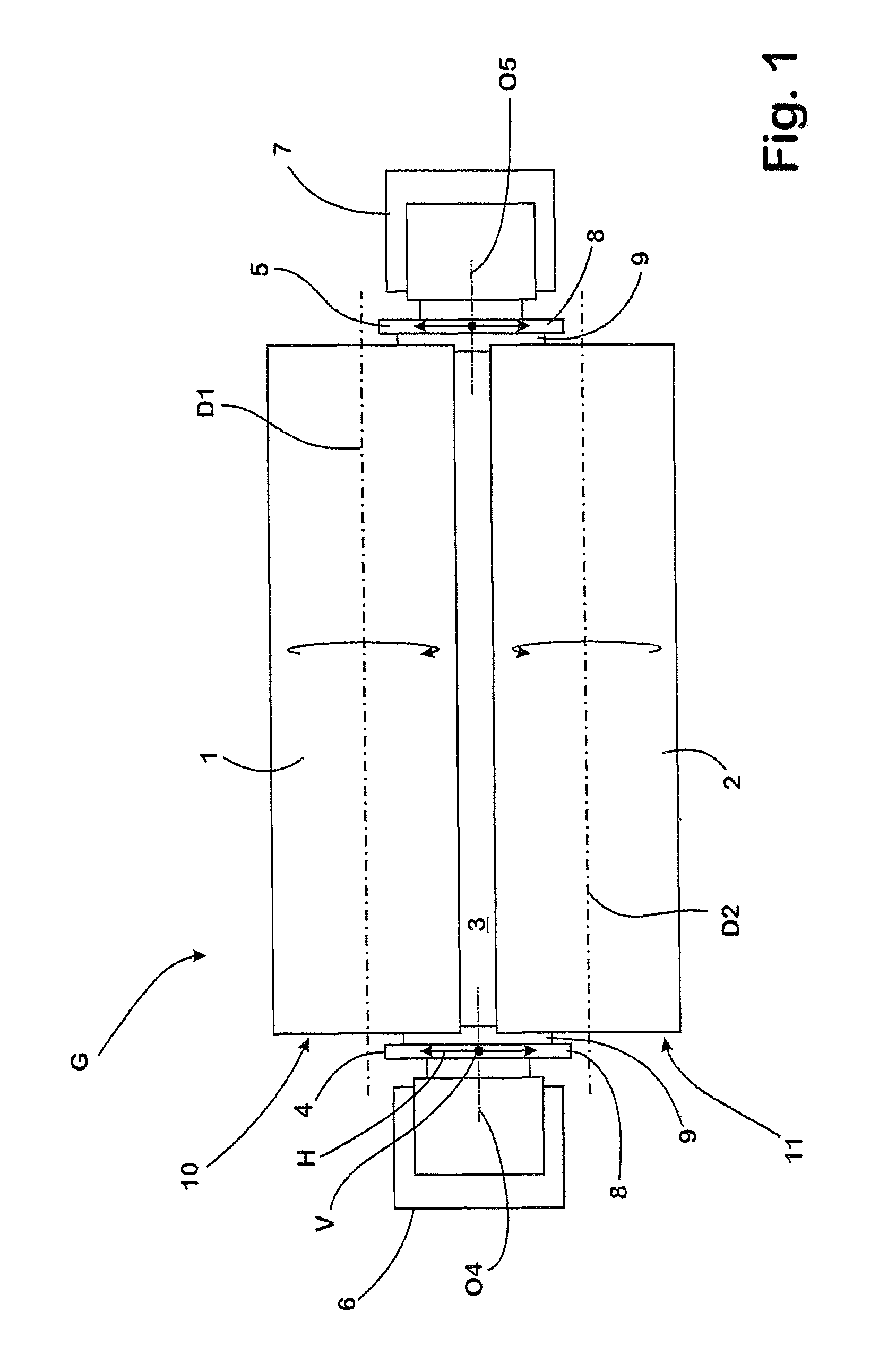
[0039]The twin roll caster G has two casting rolls 1, 2, which each rotate in the opposite direction about a horizontally aligned axis of rotation D1, D2. The casting rolls 1, 2 delimit a casting gap 3 between them on its longitudinal sides.

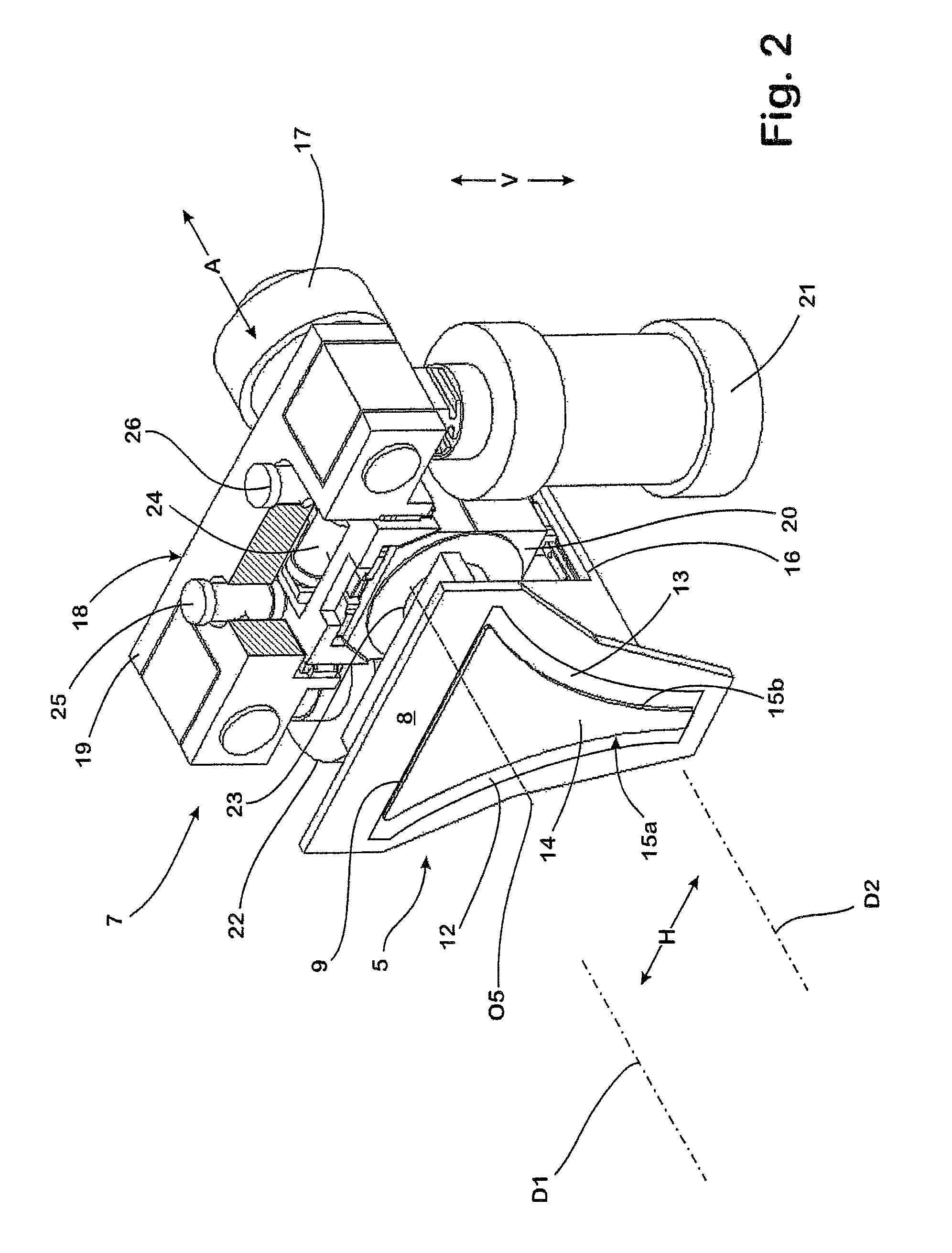
[0040]On its narrow sides the casting gap 3 is sealed by a side plate 4, 5 in each case, which is respectively supported by an adjustment device. The adjustment devices each comprise a supporting structure 6, 7. The supporting structures 6, 7 each bear an oscillation device, which oscillates the side plate 4, 5 associated with it in each case, in the casting operation about an axis of oscillation O4, O5 in each case.

[0041]The side plates 4, 5 each comprise a steel support plate 8, which on its side associated with the casting gap 3 bears an insert 9 made from a refractory material. The shape of the insert 9 is selected in such a way that it superimposes the front sides 10, 11, associated with it, of the casting rolls 1, 2 in each case in an inser...


PUM

PropertyMeasurementUnit
axes of rotationaaaaaaaaaa
forcesaaaaaaaaaa
abrasive wearaaaaaaaaaa

Abstract

A twin roll caster and method for producing strip cast from a molten metal using the twin roll caster. The twin roll caster has casting rolls which delimit a casting gap between them on its longitudinal sides and narrow sides sealed in each case by a side plate which is moved during the casting operation about an axis of oscillation in an oscillating manner. The inventive method and the twin roll caster enable the risk of operational disruptions from molten mass solidifying in the region of the side plate to be further minimized. This is achieved by changing the position of the axis of oscillation during the casting operation.

Description

BACKGROUND OF THE INVENTION[0001]When casting strip according to the twin roll casting process, the oppositely-rotating casting rolls of the caster delimit the longitudinal sides of the casting gap. On its narrow sides, however, the casting gap is sealed by a side plate in each case.[0002]The side plates are usually comprised of an insert and a support plate, which bears the insert. The insert in this case is usually made from refractory material and is formed so that it partly covers the front sides, associated with it, of the casting rolls and completely covers the narrow side, to be delimited by it, of the casting gap.[0003]The relative movements, necessary in the casting process, between the side plates and the front sides, of the casting rolls as well as the contact with the molten metal moving through the casting gap inevitably lead to wear of the side plate due to abrasive wear. This is particularly true if the contact between the side plates and the molten metal or the casti...

Claims


Application Information

Patent Timeline
Patent Type & Authority Patents(United States)
IPC IPC(8): B22D11/06
CPCB22D11/066
Inventor D'HONE, ANDRE
Owner OUTOKUMPU NIROSTA
Why Eureka
Try Eureka