
Device for feeding a rocket engine with propellant

Inactive Publication Date: 2016-07-07
ARIANEGRP SAS
View PDF36 Cites 3 Cited by
  • Summary
  • Abstract
  • Description
  • Claims
  • Application Information

AI Technical Summary

Benefits of technology

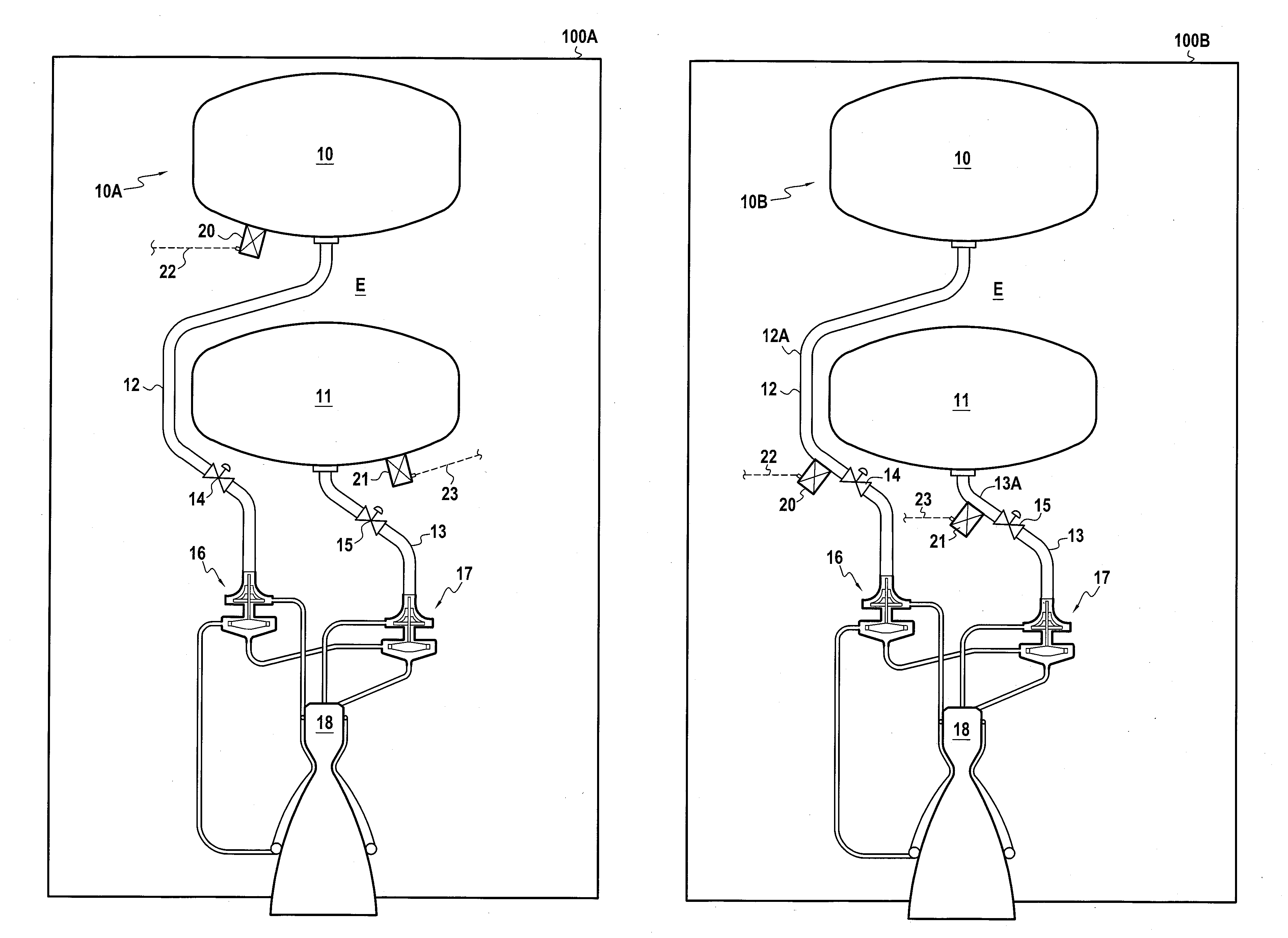
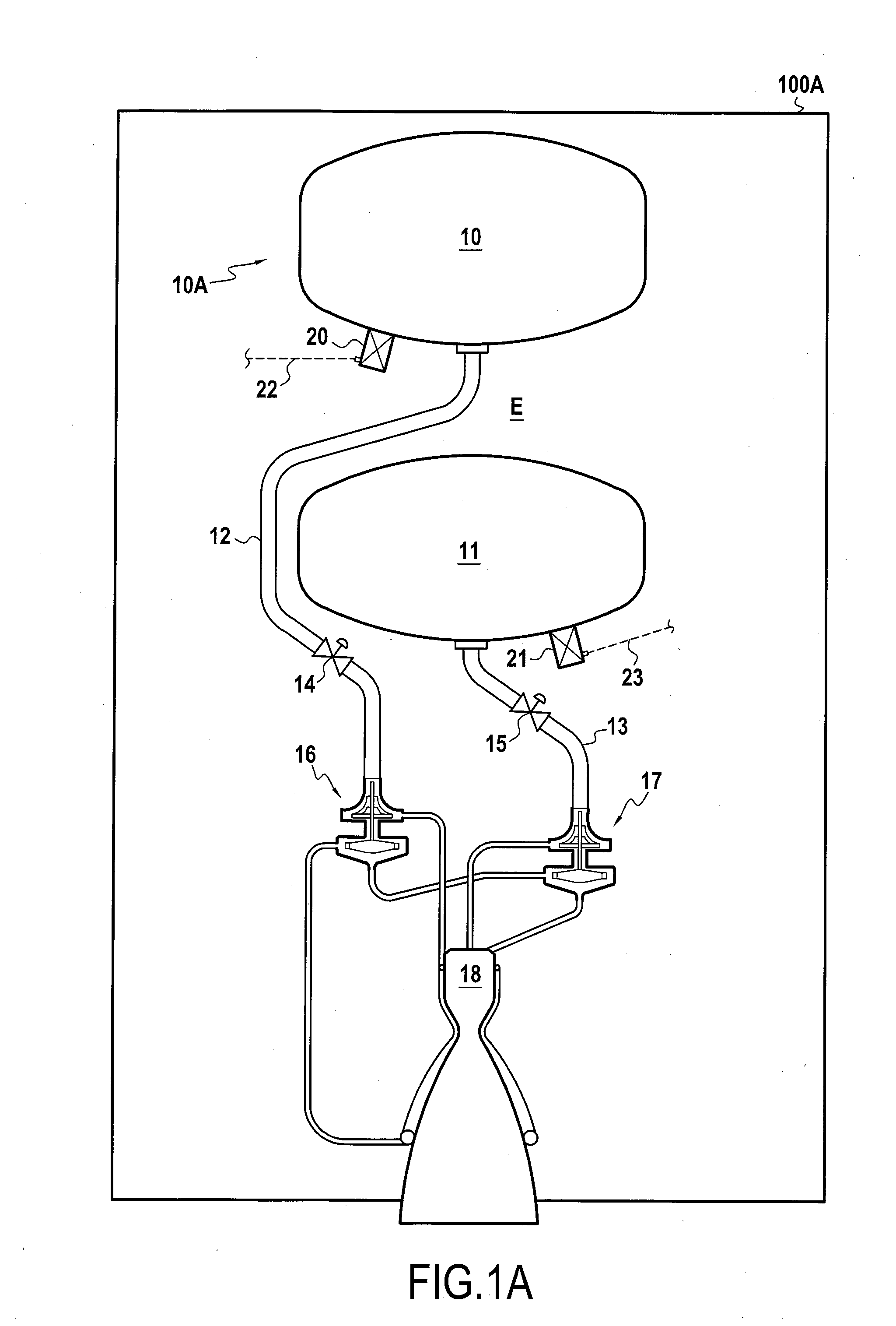
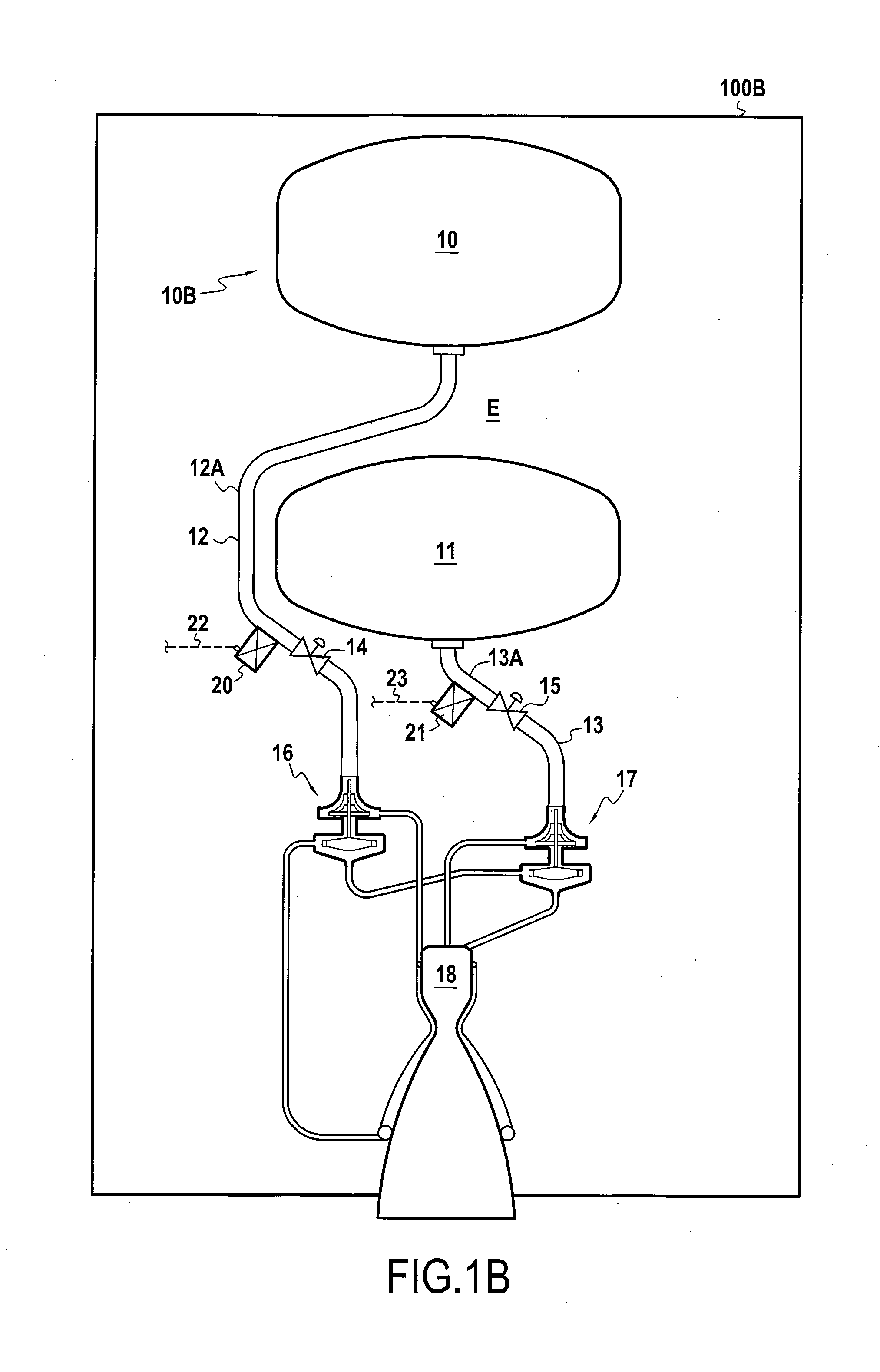
[0008]The valve makes it possible to interrupt or to authorize the feeding of propellant to the combustion chamber. Since the branch pump is connected to the tank upstream from the valve, it can be understood that the propellant from the tank can be taken off by the branch pump prior to passing through the valve. Thus, as a result of this advantageous arrangement of the branch pump within the feed device, it is possible to take off propellant in order to feed the auxiliary pipe regardless of the open or closed state of the valve. Furthermore, this makes it possible for the branch pump to operate at a very large sub-rate while minimizing any risk of operating instability and providing good suction capacity over a wide operating range.
[0009]Furthermore, since the branch pump is co

Problems solved by technology

In that known feed device, it is not easy to take off any propellant effectively for purposes other than the main

Method used


Image

  • Device for feeding a rocket engine with propellant
  • Device for feeding a rocket engine with propellant
  • Device for feeding a rocket engine with propellant

Examples


Example

[0061]FIG. 4 shows a third embodiment of the branch pump 220, in which the motor casing 240 and the fluid delivery volute 250 are arranged inside the first tank 10. The volute 250 faces the bottom wall 10′ of the first tank. The engine casing 240 is fastened to the wall 10′ of said tank 10 by means of the auxiliary pipe 222, via a fastening 222′, and by a pierced arm 246 of the engine casing 240 via a fastening 246′. The arm 246 is a hollow arm for providing an electrical connection to the stator 230 from the outside E. The fastening 222′ of the auxiliary pipe and the fastening 246′ of the arm may be any type of fastening known from elsewhere.

Example

[0062]Like the first branch pump 120 of the second embodiment, the first branch pump 220 in the third embodiment is arranged so that the volute 250 is placed directly inside the first tank 10.

[0063]In the embodiment shown in FIG. 4, the propellant is sucked in from the bottom. The major portion of the propellant is sent to the auxiliary pipe 222, while a fraction is taken off for cooling the bearings 237 and 239. This propellant fraction is taken off via the passage 248 and flows firstly through the first bearing 237 and secondly through the second bearing 239, as described above. Likewise, in a variant, the passage 248 is not provided and the first bearing 237, the wall 232, and the second bearing 239 are cooled in series by the propellant taken off from within the volute.

[0064]Although, the present invention is described with reference to specific embodiments, it is clear that modifications and changes may be made to those embodiments without going beyond the general scope of the ...


PUM


Abstract

A device (10A, 10B) for feeding a rocket engine with propellant, the device comprising at least one propellant tank (10, 11), a combustion chamber (18), and a feed pipe (12, 13) extending from the tank (10, 11) to the combustion chamber (18) to feed propellant to the combustion chamber. A valve (14, 15) and a main pump (16, 17) are arranged in succession along the feed pipe. The rocket engine device further comprises at least one branch pump (20, 21, 120, 220) making a branch connection to the tank upstream from the valve in order to feed an auxiliary pipe (22, 23, 122, 222) that serves an auxiliary function of the rocket engine.

Description

FIELD OF THE INVENTION[0001]The present invention relates to a device for feeding a rocket engine with propellant and also to a rocket engine fitted with such a propellant feed device.STATE OF THE PRIOR ART[0002]A known rocket engine propellant feed device comprises at least one propellant tank, a combustion chamber, and a feed pipe extending from the tank to the combustion chamber in order to feed propellant to the combustion chamber and having a valve and a main pump arranged in succession along the feed pipe.[0003]In that known feed device, it is not easy to take off any propellant effectively for purposes other than the main feed to the combustion chamber and to do so without significantly penalizing the performance of the rocket engine. There thus exists a need on these lines.SUMMARY OF THE INVENTION[0004]In an embodiment, the rocket engine device of the invention comprises at least one propellant tank, a combustion chamber, a feed pipe extending from the tank to the combustion...

Claims


Application Information

Patent Timeline
IPC IPC(8): F02K9/46
CPCF02K9/46B64G1/401B64G1/402F02K9/42F02K9/48F02K9/50F02K9/64F02K9/95F02K9/972
Inventor DANGUY, FRANCOISLEMAITRE, ALBANFABBRI, LAURENTPENDARIES, VINCENT
Owner ARIANEGRP SAS
Learn More