Permanent-magnet suction lift device utilizing magnetic module

A permanent magnet suction lifter, magnetic technology, applied in the direction of load hanging components, transportation and packaging, can solve the problems of reduced suction and lifting capacity, poor suction and lifting capacity of thin plates, large loss of magnetic system suction, etc. Lowering, good suction and lifting capacity, simple and clear control

Inactive Publication Date: 2014-08-06
HUNAN QIANHAO ELECTRICAL & MECHANICAL TECH DEV
View PDF7 Cites 0 Cited by
  • Summary
  • Abstract
  • Description
  • Claims
  • Application Information

AI Technical Summary

Problems solved by technology

[0002] At present, there are permanent magnet hangers on the market that control one-way rotation through ratchets, and the transmission part is composed of chains or gears. Most of them use the vertical plane to rotate the magnetic system to control the suction force of the hanger. The method has the disadvantages of large reluctance and large loss of magnetic suction force, and during the use of these suction hoists, the transmission mechanism has weak control over the magnetic system, and the synchronization is poor when multiple hoists are connected; at present, the permanent magnet suction on the market None of the hangers can achieve the function of magnetic adjustment, and the ability to absorb and lift thin plates is extremely poor
For example, a YX4 type permanent magnet hoist on the market, its transmission structure uses a lever to drive the ratchet shaft to rotate, and then drives the magnetic system to rotate through the driving sprocket and chain on the ratchet shaft, and the magnetic system uses horizontal axis rotation to control the magnetic system conversion. , when the magnetic system of this type of product is combined together, the suction capacity of the magnetic system is greatly reduced compared with that of a single magnetic system. The rotation of the magnetic system is controlled by the sprocket chain, and the rotation error is large. The magnetic system conversion control is cumbersome and the synchronization is poor

Method used


Image

  • Permanent-magnet suction lift device utilizing magnetic module
  • Permanent-magnet suction lift device utilizing magnetic module
  • Permanent-magnet suction lift device utilizing magnetic module

Examples


Embodiment Construction

[0026] The present invention will be further elaborated below in conjunction with the accompanying drawings and specific implementation examples.

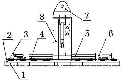
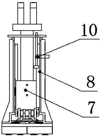
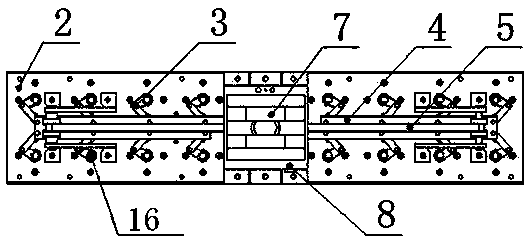
[0027] Such as figure 1 , figure 2 , image 3 , Figure 4 , Figure 5 As shown, the permanent magnet hanger of the present invention consists of a magnetic module 1, a top plate 2, a double connecting rod 3, a main connecting module 4, a pull rod 5, a main connecting module limiting unit 6, an up and down sliding module 7, and an up and down sliding module limiting unit 8 , self-locking unit 9, and magnetic modulation unit 10.

[0028] Depend on Figure 6 Schematic leverage 11, Figure 7 Schematic lever gear rack combination 12, Figure 8 Schematic connecting rod combination 13, Figure 9 The illustrated rack and pinion combination 14 and the pull rod 5 all belong to the linear motion conversion module, and their functions are to convert the up and down motion of the up and down sliding module 7 into the horizontal linear ...


PUM


Abstract

The invention discloses a permanent-magnet suction lift device utilizing a magnetic module. The permanent-magnet suction lift device mainly consists of a plurality of magnetic modules, a top plate, a mechanism fixing and limiting module and a drive mechanism, wherein the magnetic modules are fixedly arrayed and combined on the top plate and are all synchronously controlled by the drive mechanism to carry out magnetic circuit conversion so as to enable the suction lift device to externally generate or eliminate a suction force. According to the permanent-magnet suction lift device utilizing the magnetic module, a unit formation mode is adopted, the number of units can be freely combined, and the suction force and the magnetic depth of the suction lift device can be controlled by utilizing a magnetism regulation unit, so that the suction lift device has an excellent suction lift capacity.

Description

technical field [0001] The invention relates to a permanent magnet hanger, in particular to a permanent magnet hanger using a magnetic module. Background technique [0002] At present, there are permanent magnet hangers on the market that control one-way rotation through ratchet wheels, and the transmission part is composed of chains or gears. Most of them control the suction force generated by the hanger by rotating the magnetic system on a vertical plane. The method has the disadvantages of large reluctance and large loss of magnetic system suction, and these suction hoists have weak transmission mechanisms to control the magnetic system during use, and poor synchronization when multiple cranes are connected; at present, the permanent magnetic suction on the market None of the hangers can achieve the function of magnetic adjustment, and the ability to absorb and lift thin plates is extremely poor. For example, a YX4 type permanent magnet hoist on the market, its transmiss...

Claims


Application Information

Patent Timeline
Patent Type & Authority Patents(China)
IPC IPC(8): B66C1/04
Inventor 王梅千陈代新
Owner HUNAN QIANHAO ELECTRICAL & MECHANICAL TECH DEV
Why Eureka
Try Eureka