
Bandwith allocation method and routing device

a bandwidth allocation and routing method technology, applied in the field of communication technologies, can solve the problems of complicated adjustment procedure and waste of achieve the effect of saving bandwidth resources on the binding link

Active Publication Date: 2013-10-08
HUAWEI TECH CO LTD
View PDF21 Cites 0 Cited by
  • Summary
  • Abstract
  • Description
  • Claims
  • Application Information

AI Technical Summary

Benefits of technology

The present patent provides a method and device for distributing bandwidth on a network, which solves the problem of wasting bandwidth on binding links due to fixed allocation methods. The method allows for flexible allocation of bandwidth to member ports using a centralized scheduler, resulting in savings of bandwidth resources on binding links.

Problems solved by technology

According to this method, by adjusting bandwidth of each member port, an accurate value of the bandwidth limit on the binding link is finally achieved, but the adjustment needs to be operated among a plurality of physical ports, so the adjustment procedure is complicated.
The bandwidth allocation method is fixed and cannot he adjusted, and the limited bandwidth allocated to the binding link is not accurate, so that bandwidth resources on the binding link are wasted.

Method used


Image

  • Bandwith allocation method and routing device
  • Bandwith allocation method and routing device
  • Bandwith allocation method and routing device

Examples


Embodiment Construction

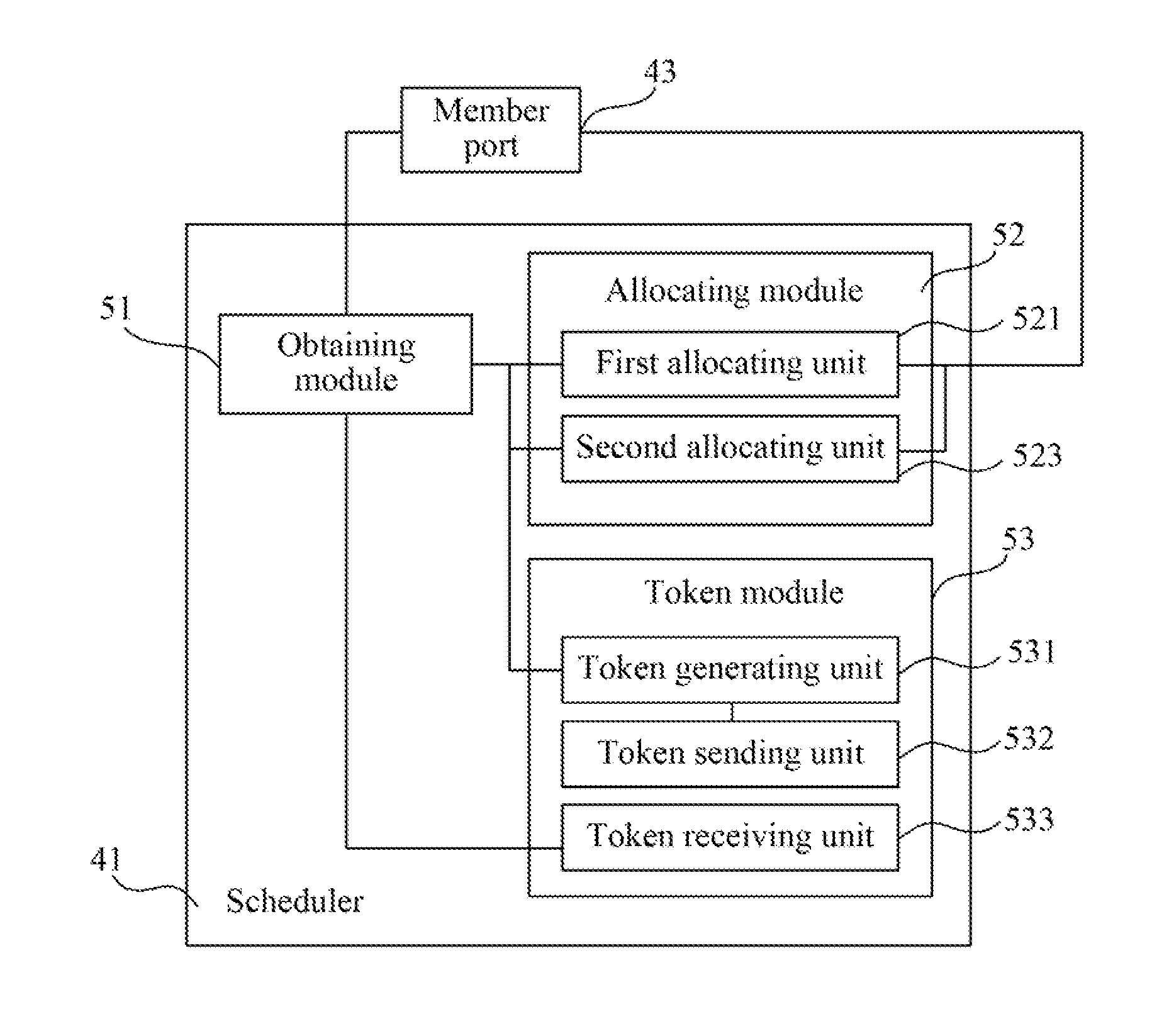
[0020]The technical solutions of the present disclosure are further described in detail through the accompanying drawings and embodiments in the following.

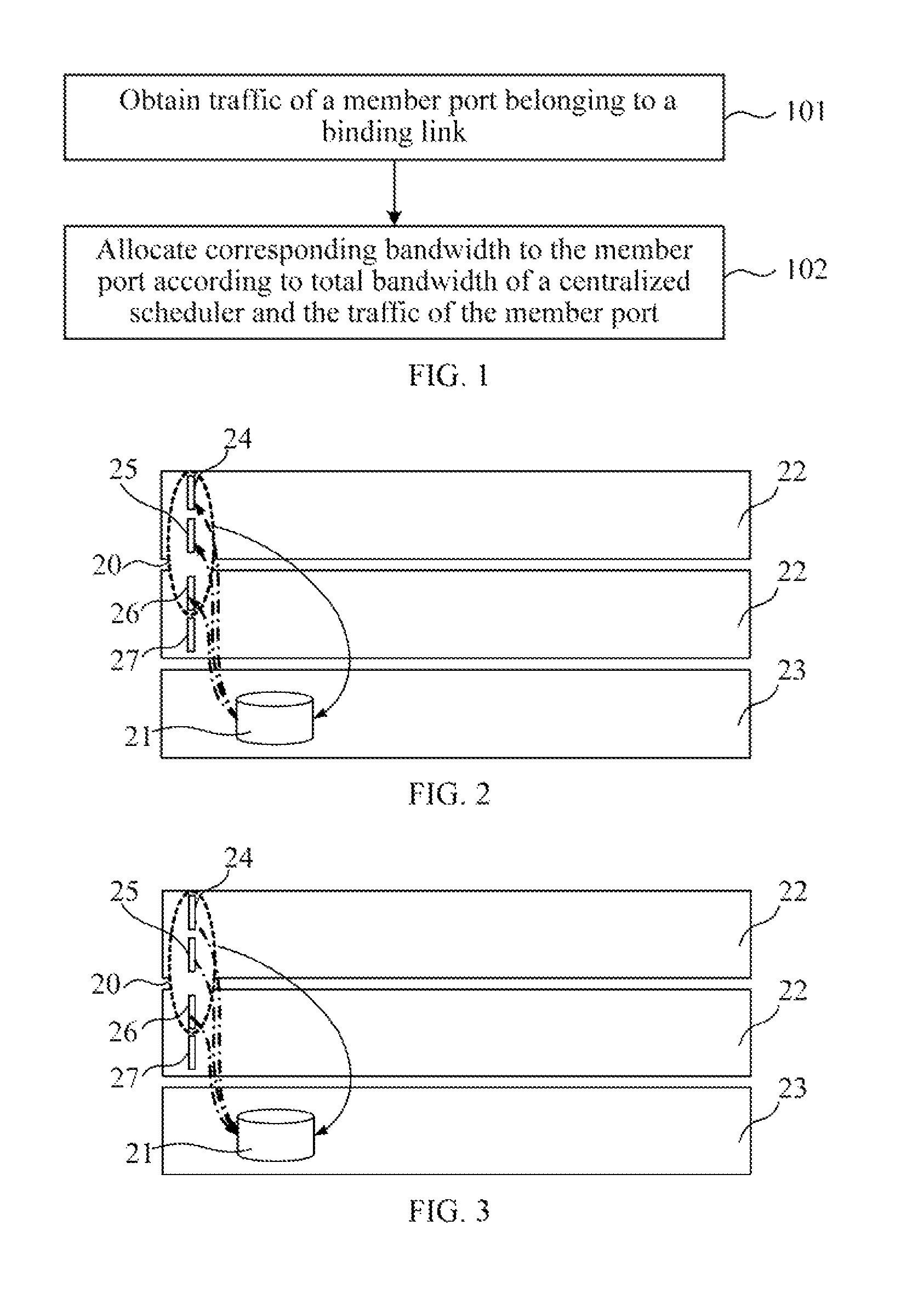
[0021]FIG. 1 is a flow chart of an embodiment of a bandwidth allocation method according to the present disclosure. As shown in FIG. 1, the bandwidth allocation method includes the following steps.

[0022]Step 101: Obtain traffic of a member port belonging to a binding link.

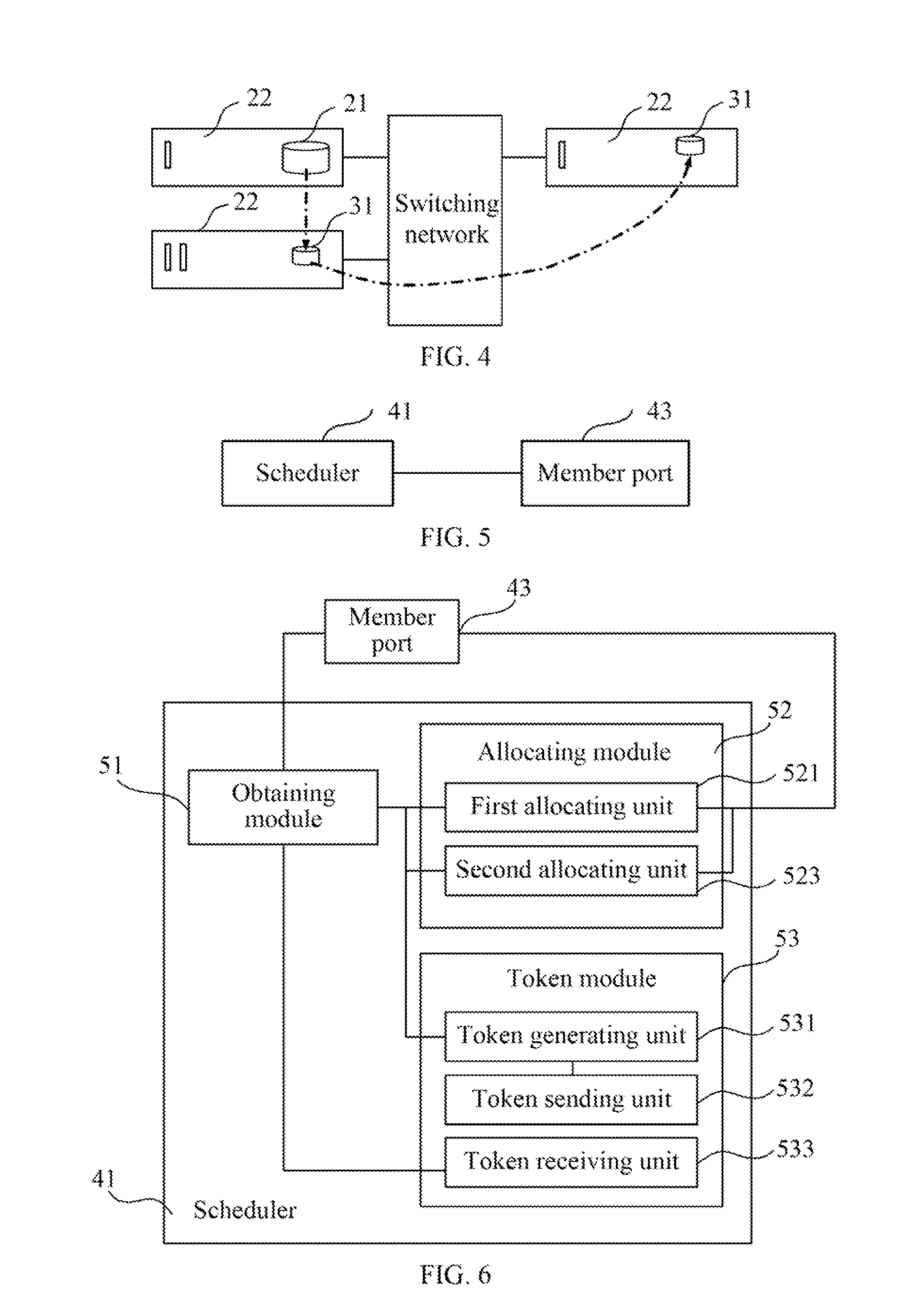
[0023]Many service processing boards configured to process specific services are provided in a communication network, and each service processing board has a plurality of physical ports. FIG. 2 is a schematic diagram of a centralized scheduler in the embodiment of the bandwidth allocation method according to the present disclosure, and FIG. 3 is a schematic diagram of another centralized scheduler in the embodiment of the bandwidth allocation method according to the present disclosure. As shown in FIG. 2 and FIG. 3, in a binding link technology, to perform centra...


PUM


Abstract

A bandwidth allocation method and a routing device are provided. The bandwidth allocation method includes: obtaining traffic of a member port belonging to a binding link (101); and allocating corresponding bandwidth to the member port according to total bandwidth of a centralized scheduler and the traffic of the member port (102). By allocating the bandwidth to the member port belonging to the binding link through the centralized scheduler, the bandwidth may be flexibly allocated to the member port according to the traffic of the member port, so that not only the accuracy of allocating the bandwidth to the member port is ensured, but also bandwidth resources on the binding link are saved.

Description

CROSS REFERENCE[0001]This application is a continuation of International Application No. PCT / CN2009 / 073400, filed on Aug. 21, 2009, which claims priority to Chinese Patent Application No. 200910076773.7, filed on Jan. 20, 2009, both of which are hereby incorporated by reference in their entireties.FIELD OF THE DISCLOSURE[0002]The present disclosure relates to the field of communications technologies, and in particular, to a bandwidth allocation method and a routing device.BACKGROUND OF THE DISCLOSURE[0003]A binding link refers to that a plurality of relevant physical ports are bound to a link to be used as a logical port. The link bound to the plurality of physical ports is called the binding link, and the physical ports bound to the binding link are called member ports of the binding link. With the rapid development of the network, the binding link is increasingly widely used. However, it is still in need of a good method for implementing bandwidth limit on the binding link. In a d...

Claims


Application Information

Patent Timeline
Patent Type & Authority Patents(United States)
IPC IPC(8): H04L12/28H04L47/21H04L45/243H04L69/14H04L47/22
CPCH04L47/215H04L47/822H04L45/245H04L47/22H04L47/781
Inventor ZHANG, YONGPINGYANG, PINGAN
Owner HUAWEI TECH CO LTD
Learn More