
Electric motors having EMI reducing circuits and methods therefor

a technology of electric motors and circuits, applied in the field of electric motor circuits, can solve the problems of electromagnetic interference, electromagnetic disturbance, adverse effects, etc., and achieve the effects of reducing electromagnetic interference, reducing electromagnetic interference (emi), and reducing electromagnetic interference (emi)

Active Publication Date: 2013-10-08
BLACK & DECKER INC
View PDF2 Cites 8 Cited by
  • Summary
  • Abstract
  • Description
  • Claims
  • Application Information

AI Technical Summary

Benefits of technology

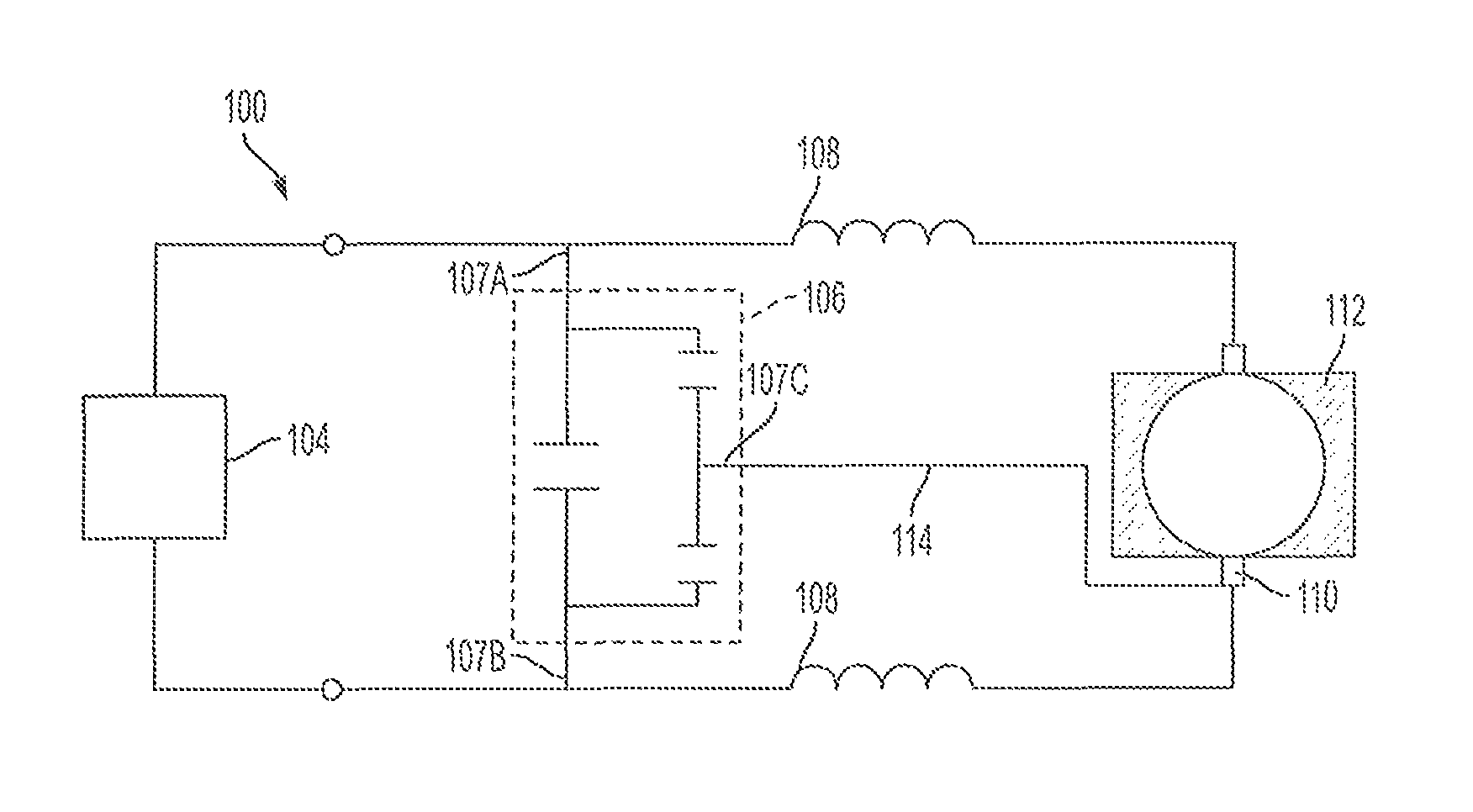
[0018]In one embodiment, a method for reducing the electromagnetic interference (EMI) emissions of an electric motor desirably includes providing a motor having a field including a field lamination stack and coils, an armature including an armature lamination stack, a shaft, a commutator mounted on the shaft, and a winding coil electrically connected to the commutator, whereby the armature is rotatably mounted within the field stack, and a brush assembly adapted to deliver electrical power to the commutator. The method preferably includes forming a circuit having a field stack, a brush assembly adapted to deliver electrical power to the field stack, motor field windings, and a delta capacitor network. The method desirably includes electrically interconnecting the delta capacitor network and the brush assembly.

Problems solved by technology

Electromagnetic interference (EMI) is a disturbance that may interrupt, obstruct, degrade or limit the effective performance of an electronic circuit or electronic device.
An EMI disturbance may result in adverse consequences including the uneven distribution of an electromagnetic field around a conductor, skin effects, proximity effects, hysteresis losses, transients, voltage drops, electromagnetic disturbances, EMP / HEMP, eddy current losses, harmonic distortion, and reduction in the permeability of a material.
EMI shielding, however, is expensive and has negative consequences.
Another method to reduce EMI involves twisting wires, however, many facilities have tens of thousands of feet of wire, so this solution is not always practical.

Method used


Image

  • Electric motors having EMI reducing circuits and methods therefor
  • Electric motors having EMI reducing circuits and methods therefor
  • Electric motors having EMI reducing circuits and methods therefor

Examples


Embodiment Construction

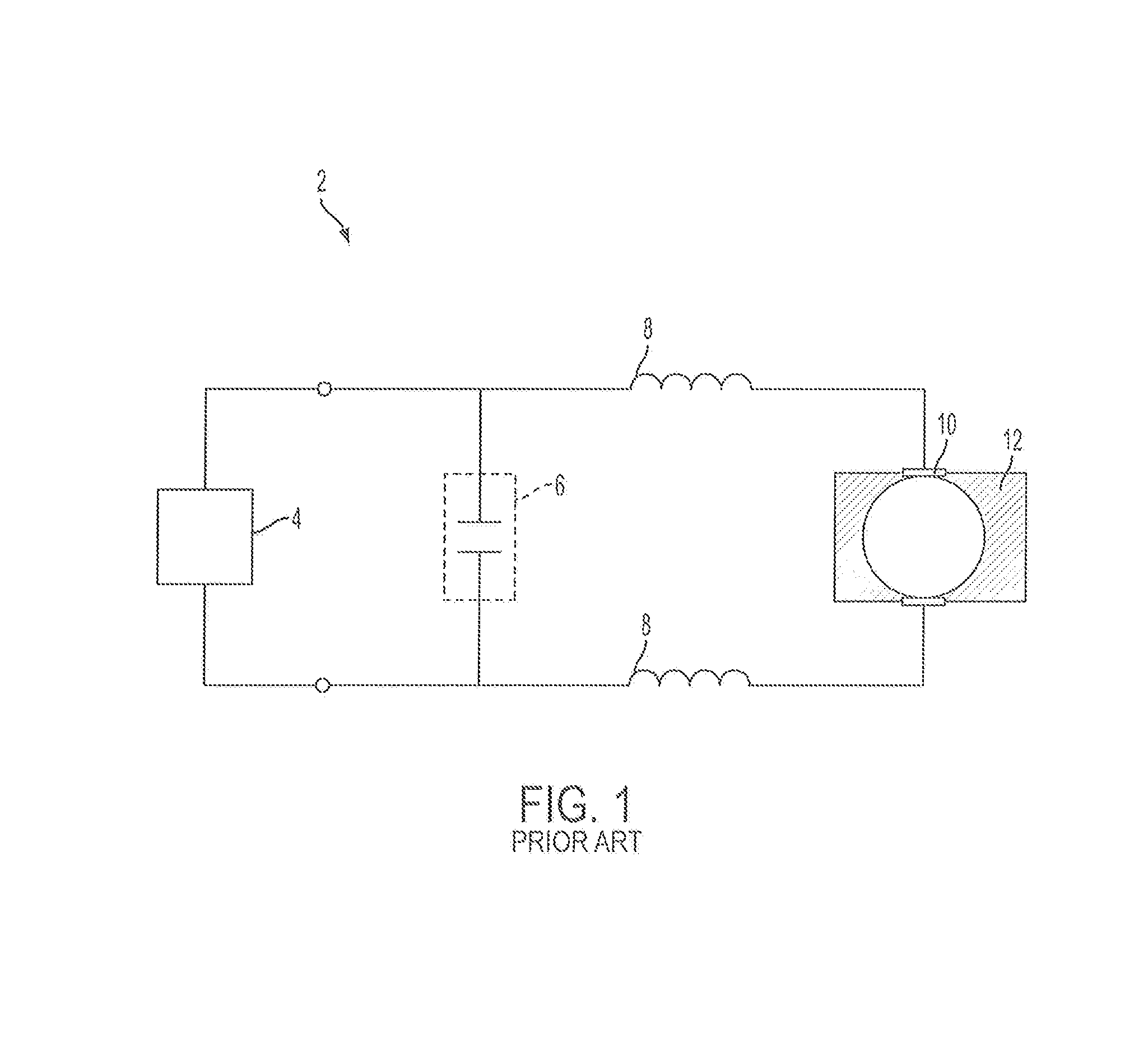
[0050]FIG. 1 shows a schematic diagram of a prior art circuit 2 for a universal electric motor. For simplicity, only some of the components of the motor circuit are illustrated. The circuit 2 includes a power source 4 connected with a two lead capacitor network 6, commonly referred to as an X capacitor network. The circuit includes motor field windings 8, brushes and a brush box 10, and a field stack 12. The power source 4 may be an alternating current (AC) or a direct current (DC) power source.

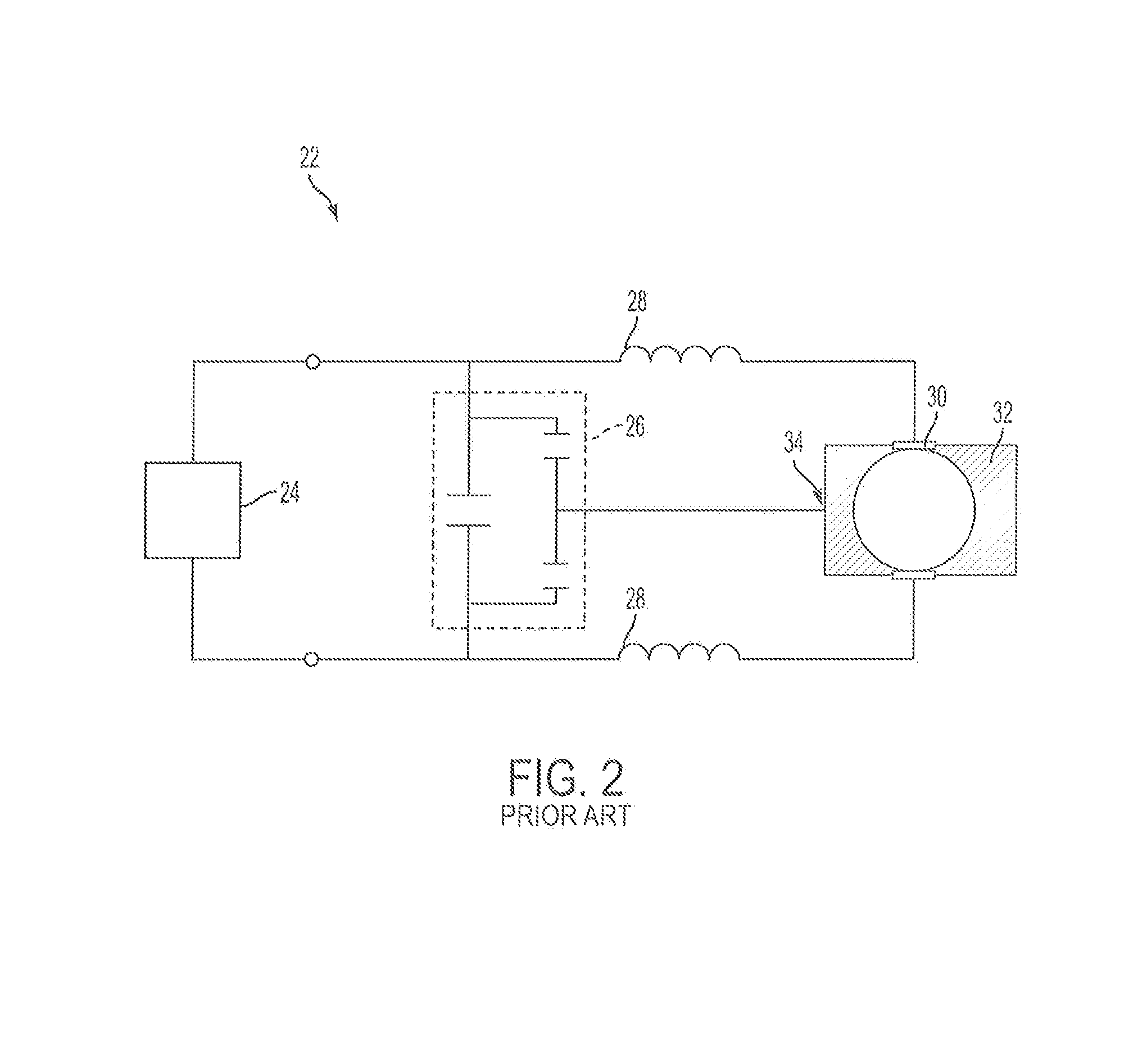
[0051]FIG. 2 shows a schematic diagram of a second prior art circuit 22 for a universal electric motor. For simplicity, only some of the components of the motor circuit are illustrated. The circuit 22 includes a power source 24, a capacitor network 16, motor field windings 28, brushes and a brush box 30, and a field stack 32. The circuit 22 also includes a lead wire 34 that interconnects one of the leads of the capacitor network 26 with the field stack 22. In the FIG. 2 embodiment, the capaci...


PUM


Abstract

An electric motor having a circuit for reducing electromagnetic interference (EMI) includes a field stack such as a stator, an armature including a shaft, a commutator mounted on the shaft, and an armature core electrically connected to the commutator, whereby the armature core is rotatably mounted within the field stack. The electric motor includes a brush assembly adapted to deliver electrical power to the commutator. The circuit includes a delta capacitor network and a conductive lead electrically interconnecting the delta capacitor network and the brush assembly. In one embodiment, the circuit includes motor field windings or coils, and a power source electrically interconnectable with the delta capacitor network and the motor field windings. In one embodiment, the motor is a universal motor.

Description

CROSS-REFERENCE TO RELATED APPLICATIONS[0001]The present application claims benefit of U.S. Provisional Application Ser. No. 61 / 187,757, entitled “CIRCUIT FOR POWER TOOL,” filed Jun. 17, 2009, the disclosure of which is hereby incorporated by reference herein.BACKGROUND OF THE INVENTION[0002]1. Field of the Invention[0003]The present invention is generally related to electronic devices, and is more specifically related to circuits for reducing electromagnetic interference (EMI) generated by electric motors.[0004]2. Description of the Related Art[0005]Electromagnetic interference (EMI) is a disturbance that may interrupt, obstruct, degrade or limit the effective performance of an electronic circuit or electronic device. An EMI disturbance may be due to either electromagnetic conduction or electromagnetic radiation emitted from a source, such as an electric motor. Electromagnetic conduction and electromagnetic radiation are differentiated by the way the electromagnetic field propagate...

Claims


Application Information

Patent Timeline
Patent Type & Authority Patents(United States)
IPC IPC(8): H02K13/00
CPCH02K11/024H02K11/026H02K11/028
Inventor ZHAO, JIANGANGGU, PAIKSONG, ZHANGHELIU, SHENGJIAN
Owner BLACK & DECKER INC
Learn More