
Panic button for data collection device

a data collection device and panic button technology, applied in substation equipment, wireless communication, instruments, etc., can solve problems such as harm to users of data collection devices

Active Publication Date: 2013-10-01
HAND HELD PRODS
View PDF12 Cites 759 Cited by
  • Summary
  • Abstract
  • Description
  • Claims
  • Application Information

AI Technical Summary

Benefits of technology

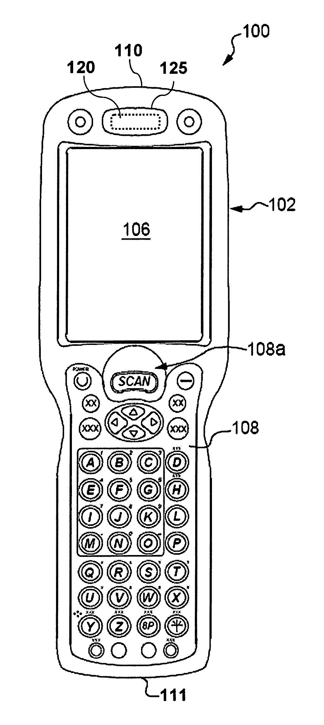
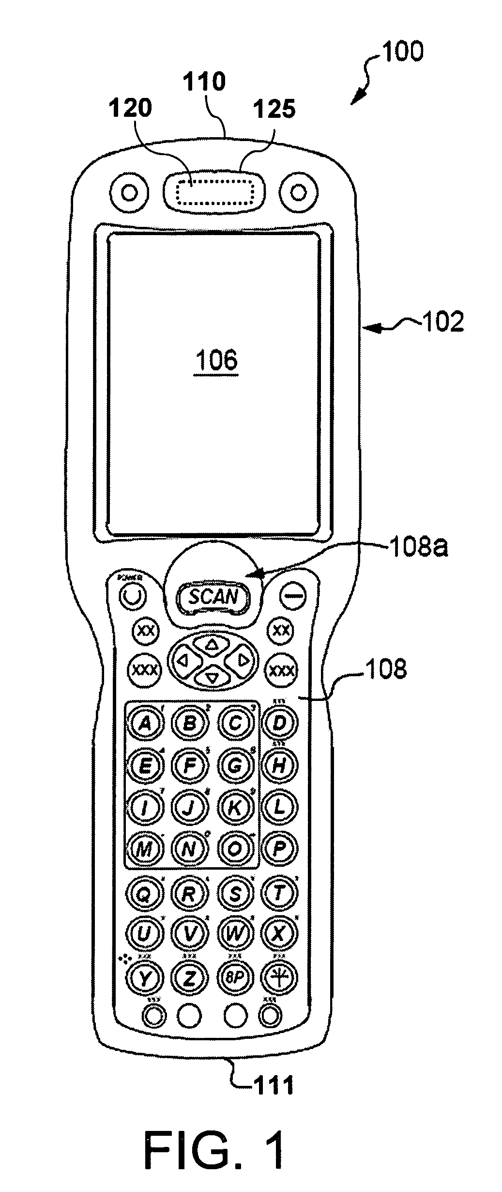
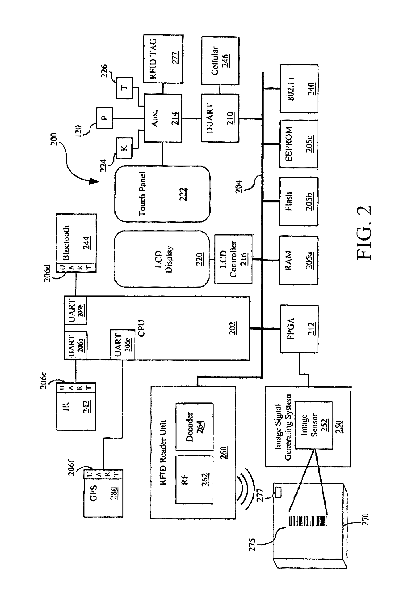
The present invention relates to improving the security of users of mobile and hand held data collection devices. The technical effects of the invention include providing apparatus and methods for securing data collected by these devices, such as fixed, mobile, and hand held devices, by incorporating features such as panic functions, secure communication paths, and secure data storage. The invention also includes a system for integrating a mobile computer, data transport paths, and data collection subsystems to facilitate secure data collection.

Problems solved by technology

Some of these activities place the user of the data collection device in harm's way.
While other types of activities may not involve the direct threat of harm, many take the user to out of the way places where obtaining help may prove difficult.

Method used


Image

  • Panic button for data collection device
  • Panic button for data collection device
  • Panic button for data collection device

Examples


Embodiment Construction

[0009]Reference will now be made in detail to embodiments of the present invention, examples of which are illustrated in the accompanying drawings, wherein like reference numerals refer to like elements throughout. It is to be noted that an element number followed by a letter generally indicates multiple occurrences of elements that are similar in structure and / or function. Further, the use of an italicized “n” associated with an element number generally denotes either an unspecified number of instances of such element or a partial or complete grouping of such elements—the meaning of which is to be drawn from the context of such use.

[0010]A method is here, and generally, conceived to be a sequence of steps or actions leading to a desired result and may be implemented as software. While it may prove convenient to discuss such software as if embodied by a single program, most implementations will distribute the described functions among discrete (and some not so discrete) pieces of so...


PUM


Abstract

A data collection device comprising: a data collection subsystem; a wireless communication device; a dedicated panic button; and a processor that, responsive to a user activating the dedicated panic button, uses the wireless communication device to cause a message to be sent to a designated emergency contact.

Description

BACKGROUND OF THE INVENTION[0001]Data collection devices are a class of device used to collect, process, and transfer data to a data processing system. Data collection devices may be provisioned with one or more of a variety of data collection sub-systems including: imager, laser scanner, RFID scanner, and magnetic media scanner. The data collection sub-systems generally scan some data bearing device such as dataforms (e.g. barcodes), magnetic stripes, and RFID tags. The collected data is processed within the data collection device by a processor and associated circuits. The type and amount of processing may vary depending on the class of device, but usually includes, at a minimum, decoding the output of the data collection sub-system to generate a string of data corresponding to the encoded data contained within the data bearing device. The decoded data may then be transferred using any number of wired and wireless communication paths, such as 802.11, cellular, IrDA, USB, serial an...

Claims


Application Information

Patent Timeline
Patent Type & Authority Patents(United States)
IPC IPC(8): H04M11/04
CPCH04M1/72541H04M2250/10H04M2250/12H04M2250/22H04M1/72424
Inventor GRUNOW, JONATHAN T.VAN ETTEN, DAVID
Owner HAND HELD PRODS
Learn More