
Cleaning apparatus and image forming apparatus

a technology of cleaning apparatus and cleaning roller, which is applied in the direction of electrographic process apparatus, instruments, optics, etc., can solve the problems of not being able to obtain superior transfer images, not being able to maintain the thickness of the toner layer formed on the surface of the cleaning roller (d) uniform, and not being able to consistently polish a photosensitive drum

Active Publication Date: 2013-09-24
KYOCERA DOCUMENT SOLUTIONS INC
View PDF10 Cites 0 Cited by
  • Summary
  • Abstract
  • Description
  • Claims
  • Application Information

AI Technical Summary

Benefits of technology

[0022]It is an object of aspects of the present invention to provide a cleaning apparatus and an image forming apparatus that, even when the quantity of toner supplied to a cleaning roller varies, make it possible to adjust the thickness of a toner layer that is formed on the surface of the cleaning roller and thereby consistently polish the surface of a photosensitive drum, and to also perform consistent polishing of a photosensitive drum over an extended period of time without the members forming the cleaning apparatus becoming worn.

Problems solved by technology

This residual toner or electrical discharge product prevents (impedes) the forming of new images, and is a main cause for superior transfer images not being obtained.
However, in the conventional cleaning apparatus (a), because the amount of toner held on the cleaning roller (d) is not constant, keeping the thickness of the toner layer formed on the surface of the cleaning roller (d) uniform has proved problematic.
Accordingly, in the cleaning apparatus (a) having the above described structure, it has not been possible to consistently polish a photosensitive drum.
However, if an excessive quantity of toner is adhering to the surface of the photosensitive drum, the quantity of toner that is accumulated in the toner receive also becomes excessive, and there is a possibility that the quantity of toner held on the cleaning roller will become too great and will re-adhere to the photosensitive drum.
Moreover, if the toner quantity adhered on the surface of the photosensitive drum is too small, then sufficient polishing cannot be achieved and it becomes necessary to supply toner.
Accordingly, because the polishing effect varies as the toner quantity increases and decreases, it is difficult to achieve consistent polishing.
However, there is a possibility that the above described scraper will remove too much of the toner held on the cleaning roller, and in this case the problem arises that friction between the cleaning roller and the scraper causes the toner to become fused to the respective members.
Furthermore, if this apparatus is used for a lengthy period of time, the problems arises that portions of the scraper become worn away and uniform polishing is no longer possible.
Namely, as a result of portions of the scraper being worn away, it is no longer possible to adjust the quantity of toner on the cleaning roller and the thickness of the toner layer on the cleaning roller increases.
Because of this, the polishing of the surface of the photosensitive drum becomes excessive.
Moreover, because the toner layer is thinner in those areas which are scraped by the non-worn portions of the scraper than those in areas which are scraped by the worn portions of the scraper, the pressing force with which the cleaning roller presses against the photosensitive drum is reduced and sufficient polishing is not possible.
Accordingly, it is difficult to consistently polish a photosensitive drum over an extended period of time.

Method used


Image

  • Cleaning apparatus and image forming apparatus
  • Cleaning apparatus and image forming apparatus
  • Cleaning apparatus and image forming apparatus

Examples


example 1

[0100]A cleaning apparatus according to an embodiment of the present invention was loaded (mounted) in an image forming apparatus (a TASK alfa 500ci), and the thickness of the toner layer formed on the cleaning roller after printing was evaluated.

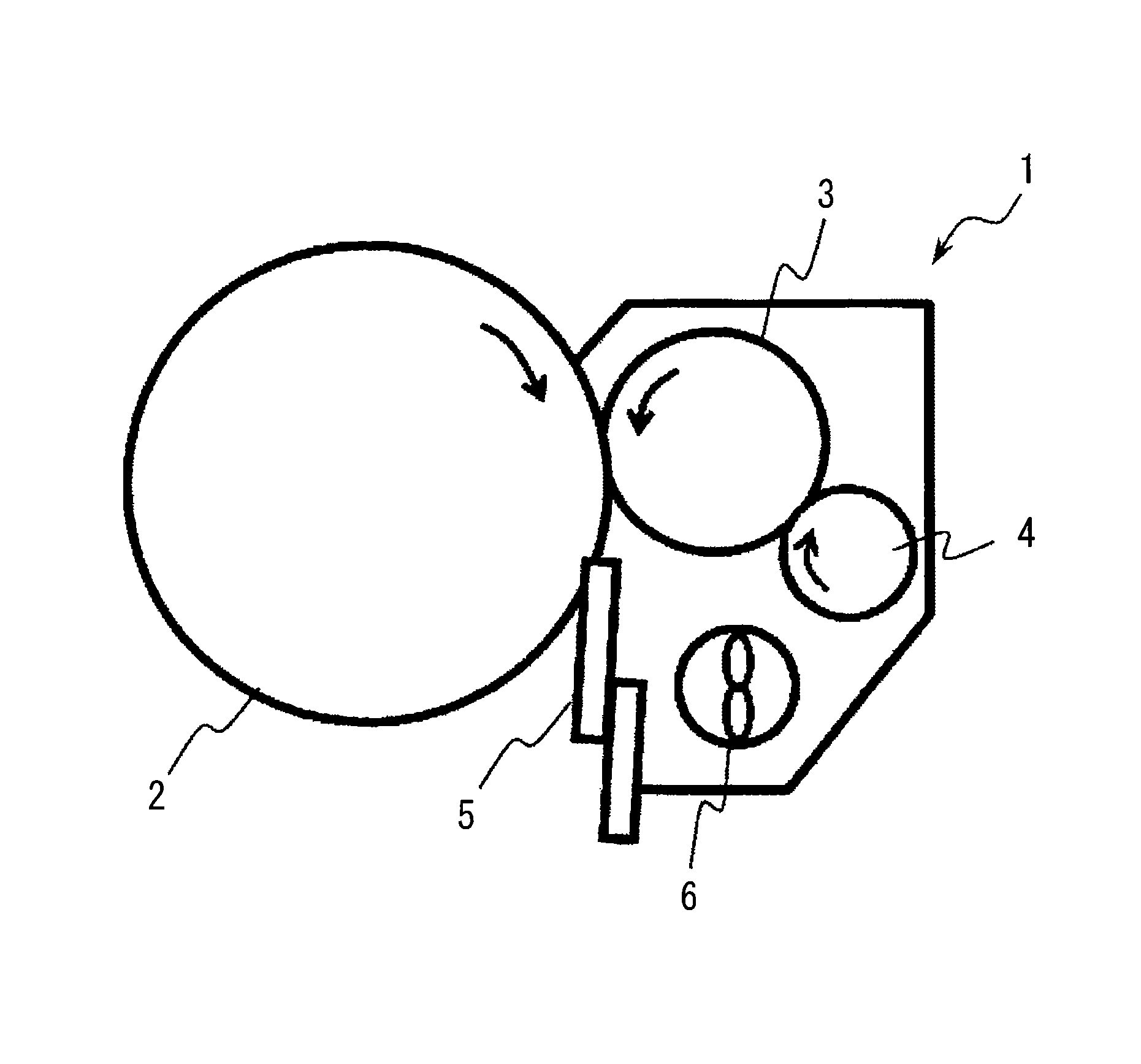
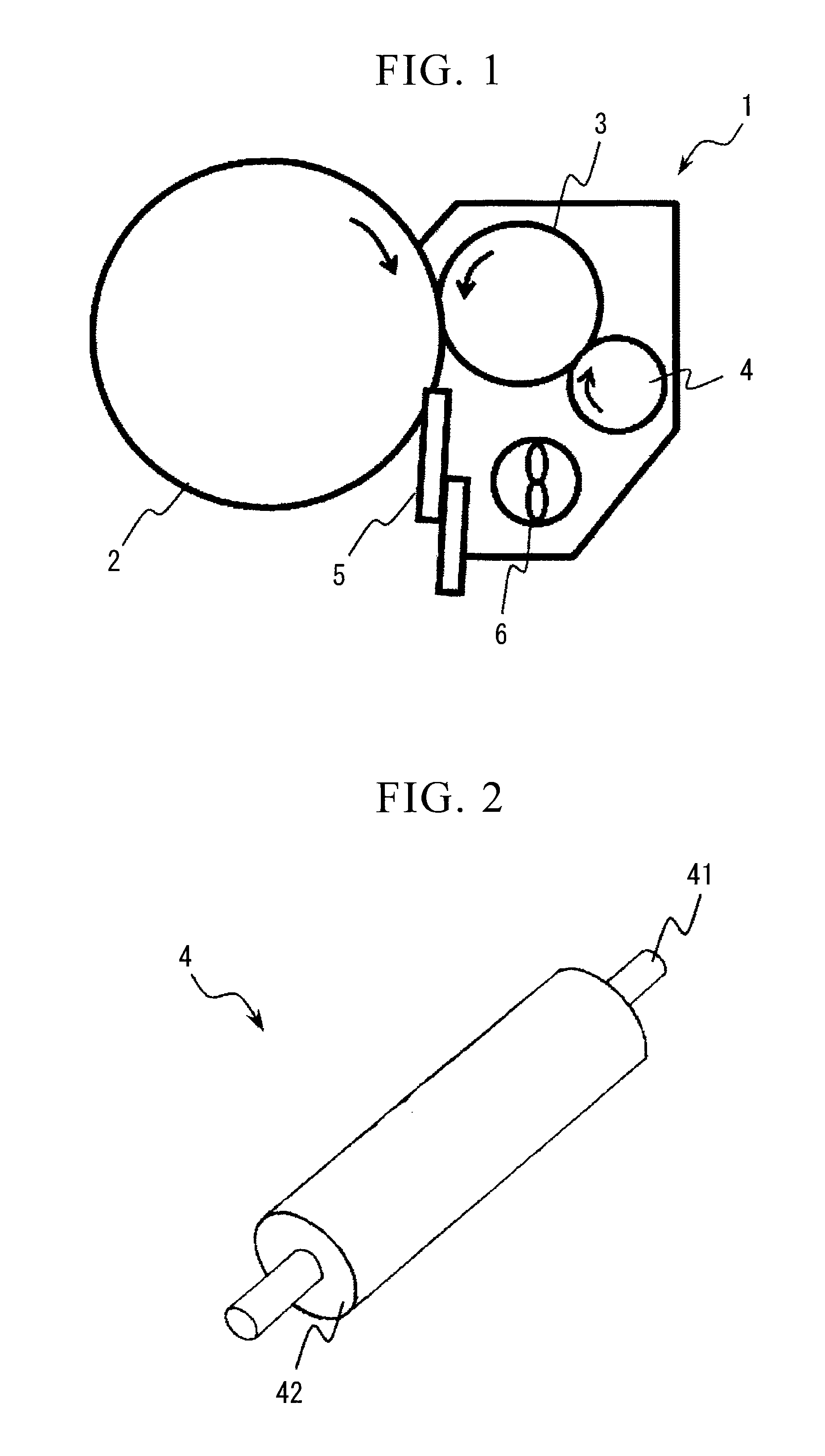
[0101]A cleaning apparatus provided with the structure shown in FIG. 1 was used, and urethane foaming rubber (having an outer diameter of 15.5 mm and a thickness of 1.75 mm) was used for the cleaning roller, a urethane rubber plate (having a thickness of 2.2 mm) was used for the cleaning blade, and a sponge roller (made of urethane having an outer diameter of 11 mm and a thickness of 1.5 mm) was used for the toner layer thickness regulating roller. Moreover, the outermost layer of the photosensitive drum was formed from amorphous silicon, and titanium oxide (TiO2) was externally added to the toner.

[0102]The linear velocity of the photosensitive drum was set to 210 mm / sec, and the linear velocity of the cleaning roller was set to 168 min / sec...

example 2

[0114]A cleaning apparatus provided with the structure shown in FIG. 1 was used, and the thickness of toner layers formed on the cleaning roller was evaluated. An EPDM foaming body (having an outer diameter of 15 mm and a thickness of 2 mm) was used for the cleaning roller, a urethane rubber plate (having a thickness of 2.2 mm) was used for the cleaning blade, and a brush roller (made of conductive nylon at 120 KF / inch2, 330T / 48F, and having a shaft of 6 mm and a bristle length of 3 mm) was used for the toner layer thickness regulating roller. Moreover, the outermost layer of the photosensitive drum was formed from amorphous silicon, and titanium oxide (TiO2) was externally added to the toner.

[0115]The rotation directions of the cleaning roller and toner layer thickness regulating roller were the same direction at the point where the two rollers contacted each other, and the development of a solid pattern having a width of 50 mm in the circumferential direction of the photosensitive...

example 3

[0123]A toner layer was formed on a cleaning roller using the same method as that employed in Example 2. After the cleaning roller and the toner layer thickness regulating roller had been rotated at different speeds, the toner layer thickness was measured. The thickness of the toner layer was measured in five locations in the axial direction of the cleaning roller, and the mean value thereof was calculated.

[0124]The linear velocity of the photosensitive drum was set to 210 mm / sec, and the linear velocity of the cleaning roller was set to 168 mm / sec. The toner layer thickness regulating roller was then rotated at linear velocities of 0.6, 0.8, 1 (i.e., in slave rotation), 1.2, and 1.4 times that of the cleaning roller.

[0125]The results are shown in Table 3.

[0126]

TABLE 3Linear velocity ratioMean value of cleaningrelative to that ofroller toner layercleaning rollerthickness (μm)0.6150.8301451.2351.420

[0127]From Table 3 it was found that as the difference in velocity relative to that of...


PUM


Abstract

A cleaning apparatus is provided with a cleaning roller that is positioned so as to be in contact with a photosensitive drum, and with a toner layer thickness regulating member that regulates the thickness of a toner layer adhering to the surface of this cleaning roller. The toner layer thickness regulating member is formed by a toner layer thickness regulating roller that rotates in contact with the cleaning roller.

Description

BACKGROUND OF THE INVENTION[0001]1. Field of the Invention[0002]The present invention relates to a cleaning apparatus that is used in an image forming apparatus such as a copy machine or printer, and also relates to an image forming apparatus that is provided with this cleaning apparatus.[0003]Priority is claimed on Japanese Patent Application No. 2009-295799, filed Dec. 25, 2009 and Japanese Patent Application No. 2009-295800, filed Dec. 25, 2009, the contents of which are incorporated herein by reference.[0004]2. Description of Related Art[0005]In an image forming apparatus such as a copy machine or printer, a photosensitive drum is provided in an image forming section. An electrostatic latent image is formed on the surface of this photosensitive drum, and toner is then adhered thereto resulting in a toner image being formed.[0006]The toner image is then transferred onto a transfer body such as copy paper, however, the toner does not get completely transferred and a portion thereo...

Claims


Application Information

Patent Timeline
Patent Type & Authority Patents(United States)
IPC IPC(8): G03G21/00
CPCG03G21/0058G03G2221/1627
Inventor KOBAYASHI, KIYOTAKAMURATA, TAKAHIKOTAKAGAMI, AISHIMIZU, YOSHIMIGODA, MITSUHIROHANANO, SUSUMUTSUJI, HIROFUMIHATAKEYAMA, CHISATOOTA, KATSUYA
Owner KYOCERA DOCUMENT SOLUTIONS INC
Learn More