High-linearity testing stimulus signal generator

a high-linearity, stimulus technology, applied in the field of signal generators, can solve the problems of high cost, unpractical test results, and high resolution of high-resolution digital-to-analog converters built in chips, and achieve the effect of reducing the high cost of high-linearity testing stimulus generators

Inactive Publication Date: 2013-09-24
NATIONAL YUNLIN UNIVERSITY OF SCIENCE AND TECHNOLOGY
View PDF4 Cites 1 Cited by
  • Summary
  • Abstract
  • Description
  • Claims
  • Application Information

AI Technical Summary

Benefits of technology

[0006]Another objective of the present invention is to reduce the high cost of high-linearity testing stimulus generators.

Problems solved by technology

Consequently, the test results are usually unpractical.
The fundamental problems of a ramp generator include whether the linearity of signals can be used for testing the circuit under test having higher and higher resolution, whether it is expensive, whether the test result thereof is as accurate as expected when considering the non-ideality of the fabrication process, whether it can overcome the factors of environmental interference, probe pointing, loads, etc., and whether it is practical to generate testing stimulus signals externally to input to a chip in case of SOC (System-on-a-Chip).
However, a high-resolution digital-to-analog converter built in a chip not only is expensive but also increases the complexity of design and integration of the chip.
However, the method can only apply to a chip where a constant current source 1 and a capacitor 2 exist simultaneously.

Method used


Image

  • High-linearity testing stimulus signal generator
  • High-linearity testing stimulus signal generator
  • High-linearity testing stimulus signal generator

Examples


Embodiment Construction

[0017]The technical contents of the present invention are described in detail in cooperation with the drawings below.

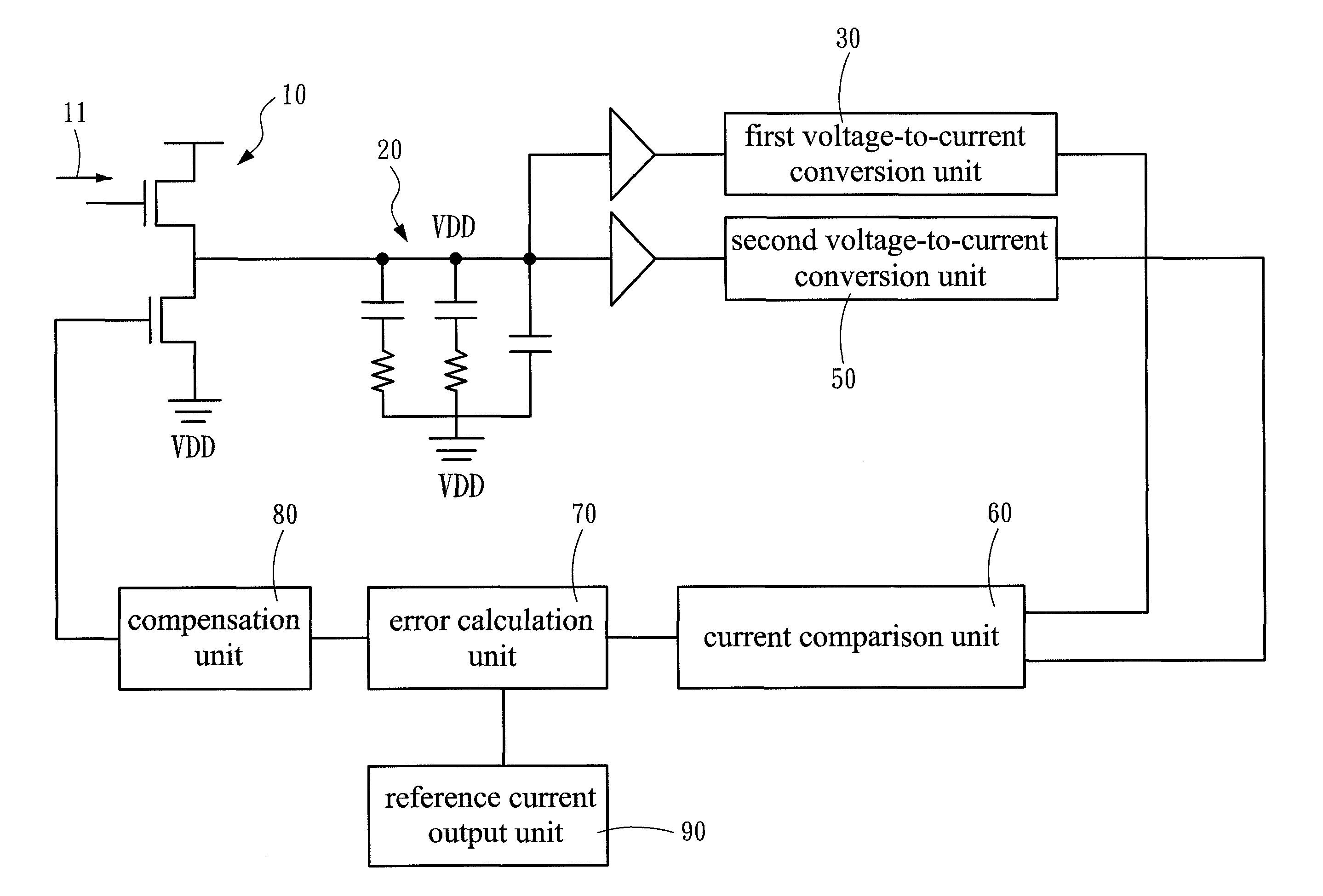
[0018]Refer to FIG. 3A and FIG. 3B. FIG. 3A is a block diagram schematically showing the architecture of a high-linearity testing stimulus signal generator according to one embodiment of the present invention. FIG. 3B is a diagram showing the waveform of signals according to one embodiment of the present invention. The present invention proposes a high-linearity testing stimulus signal generator, which comprises a signal collection unit 10, a waveform conversion unit 20, a first voltage-to-current conversion unit 30, a delay unit 40, a second voltage-to-current conversion unit 50, a current comparison unit 60, an error calculation unit 70, and a compensation unit 80.

[0019]The signal collection unit 10 receives an input current signal 11 and outputs a signal. The waveform conversion unit 20 connects with the signal collection unit 10, converts the signal output by the ...


PUM


Abstract

A high-linearity testing stimulus signal generator comprises a signal collection unit receiving an input current signal, a waveform conversion unit connecting with the signal collection unit, a first voltage-to-current conversion unit connecting with the waveform conversion unit, a delay unit connecting with the waveform conversion unit, a second voltage-to-current conversion unit connecting with the delay unit, a current comparison unit connecting respectively with the first voltage-to-current conversion unit and the second voltage-to-current conversion unit, an error calculation unit connecting with the current comparison unit, and a compensation unit connecting with the error calculation unit. The above-mentioned structure forms a feedback mechanism to perform compensation adjustment to promote the linearity of the output signals. Thus, the present invention can generate high-accuracy testing stimulus signals.

Description

FIELD OF THE INVENTION[0001]The present invention relates to a signal generator, particularly to a high-linearity testing stimulus signal generator.BACKGROUND OF THE INVENTION[0002]With the advance of information technology, the audio / video files need higher and higher resolution and demand greater and greater storage capacity. A high-quality terminal device should be equipped with a high-performance data transmission system to transmit an enormous amount of data. Thus, ADC (Analog to Digital Converter), which functions as a conversion interface, demands higher and higher specification, some of which may be far beyond the range that the testing stimulus signal generators can operate. Hence, the high-resolution ADC is usually performed verification by lowering the resolution thereof during testing. Consequently, the test results are usually unpractical.[0003]A US Publication No. 20090040199 entitled an “Apparatus for Testing Driving Circuit for Display” discloses an analog-to-digital...

Claims


Application Information

Patent Timeline
Patent Type & Authority Patents(United States)
IPC IPC(8): G06G7/12
CPCG06G7/26
Inventor LIN, CHUN-WEIWU, YI-CANG
Owner NATIONAL YUNLIN UNIVERSITY OF SCIENCE AND TECHNOLOGY
Why Eureka
Try Eureka