
Multi-thread processor selecting threads on different schedule pattern for interrupt processing and normal operation

a multi-thread processor and schedule pattern technology, applied in the field of multi-thread processors, can solve the problems of system error, process itself in which the rewriting of this register and the like is carried out, and could become significant overhead, so as to achieve the effect of curtailing the processing of significant overhead such as the schedule rewriting process

Active Publication Date: 2013-09-17
RENESAS ELECTRONICS CORP
View PDF8 Cites 8 Cited by
  • Summary
  • Abstract
  • Description
  • Claims
  • Application Information

AI Technical Summary

Benefits of technology

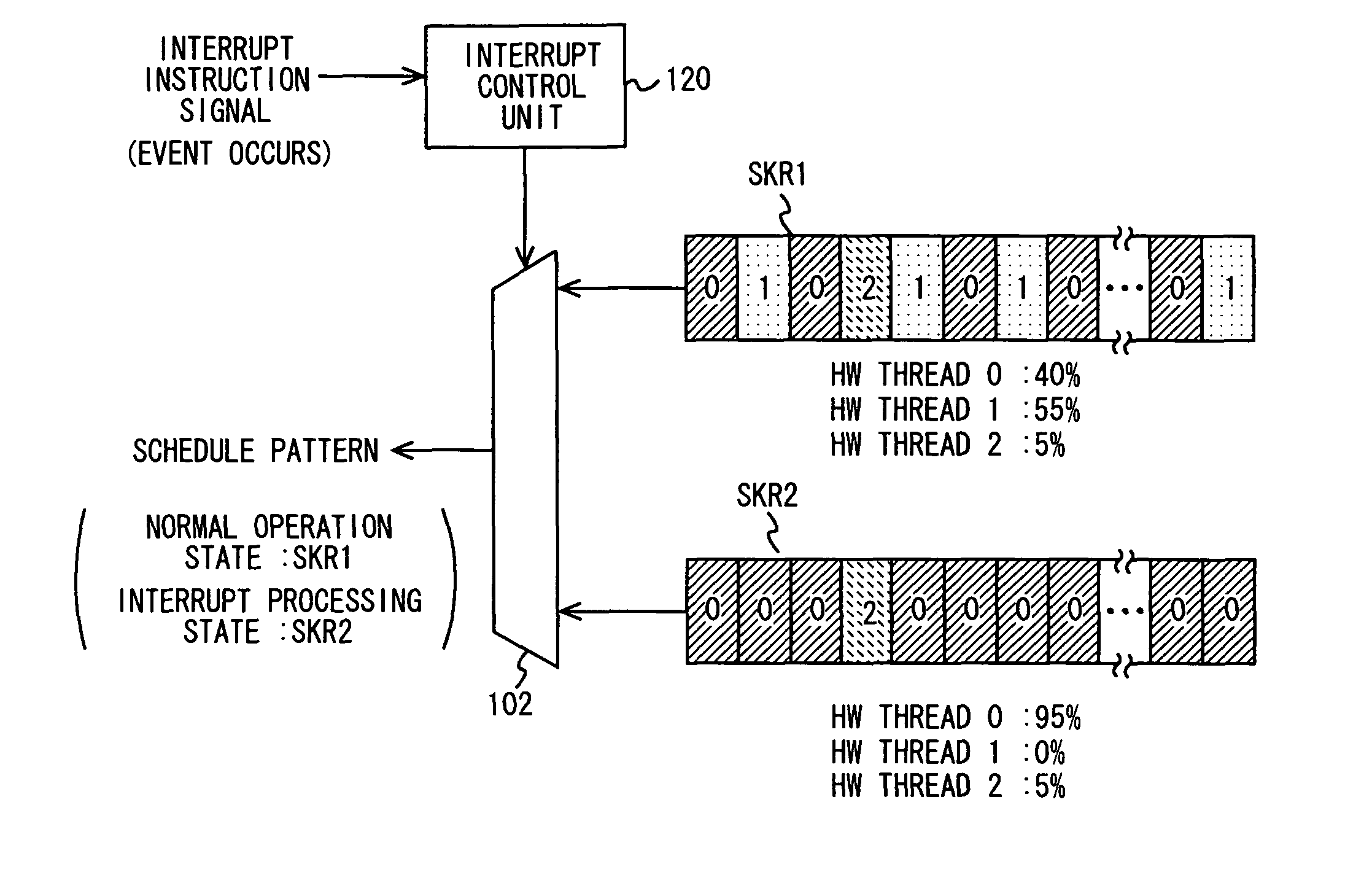
[0011]The multi-thread processor in accordance with an exemplary aspect of the present invention includes first and second schedules, and when the state of the processor is changed from the first state to the second state, the multi-thread processor can change the schedule from the first schedule to the second schedule. In this way, when the state of the processor is changed, the processing involving significant overhead such as the schedule rewriting process can be curtailed.
[0012]In accordance with a multi-thread processor in accordance with an exemplary aspect of the present invention, when the state of the processor is changed, a thread schedule can be swiftly selected according to that state of the processor.

Problems solved by technology

Therefore, there is a possibility that the processing power required by the system for interrupt processing having a high priority such as communication control of real-time data is not sufficiently obtained, and thereby causing a system error.
However, in interrupt processing in which the presence or absence of several clocks is critical, this process itself in which rewriting of this register and the like are carried out could become significant overhead.

Method used


Image

  • Multi-thread processor selecting threads on different schedule pattern for interrupt processing and normal operation
  • Multi-thread processor selecting threads on different schedule pattern for interrupt processing and normal operation
  • Multi-thread processor selecting threads on different schedule pattern for interrupt processing and normal operation

Examples


first exemplary embodiment

[0033][First Exemplary Embodiment]

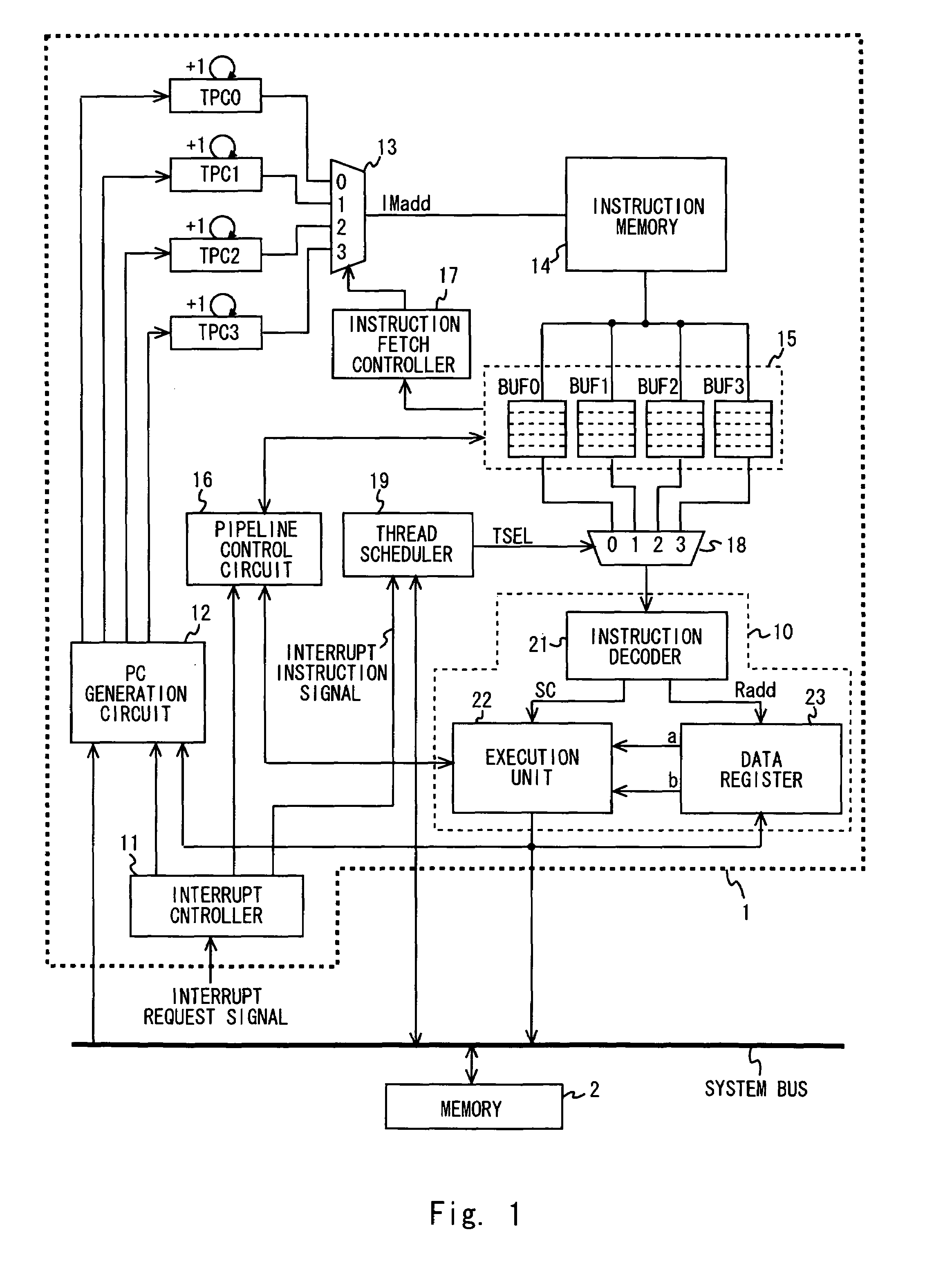
[0034]A specific first exemplary embodiment to which the present invention is applied is explained hereinafter in detail with reference to the drawings. FIG. 1 is a block diagram of a processor system including a multi-thread processor 1 in accordance with a first exemplary embodiment of the present invention. A multi-thread processor 1 is connected to a memory 2 through a system bus in a processor system in accordance with this exemplary embodiment. Note that though they are not shown in the figure, other circuits such as input / output interfaces are also connected to the system bus.

[0035]Firstly, a multi-thread processor 1 in accordance with this exemplary embodiment of the present invention is explained hereinafter. The multi-thread processor 1 includes a plurality of hardware threads. The hardware threads are composed of a group of circuits including thread program counters, an instruction memory, a general register, and a control register (it is...

second exemplary embodiment

[0079][Second Exemplary Embodiment]

[0080]A specific second exemplary embodiment to which the present invention is applied is explained hereinafter in detail with reference to the drawings. The configuration of a second exemplary embodiment of the present invention is different from that of the first exemplary embodiment in that the thread schedule register SKR2 of the thread control resister unit 101 is changed to a thread schedule register SKR3. Note that the change to the thread schedule register SKR3 is not a physical change of the register, and it may include a case where the schedule pattern retained in the register is rewritten from SKR2 to SKR3. Other configurations are same as those of the first exemplary embodiment, and therefore their explanation is omitted.

[0081]The thread schedule register SKR3 has a hardware thread number that enables the multi-thread processor 1 to perform specific fixedly-scheduled operations. In this example, the thread schedule register SKR3 has onl...

third exemplary embodiment

[0089][Third Exemplary Embodiment]

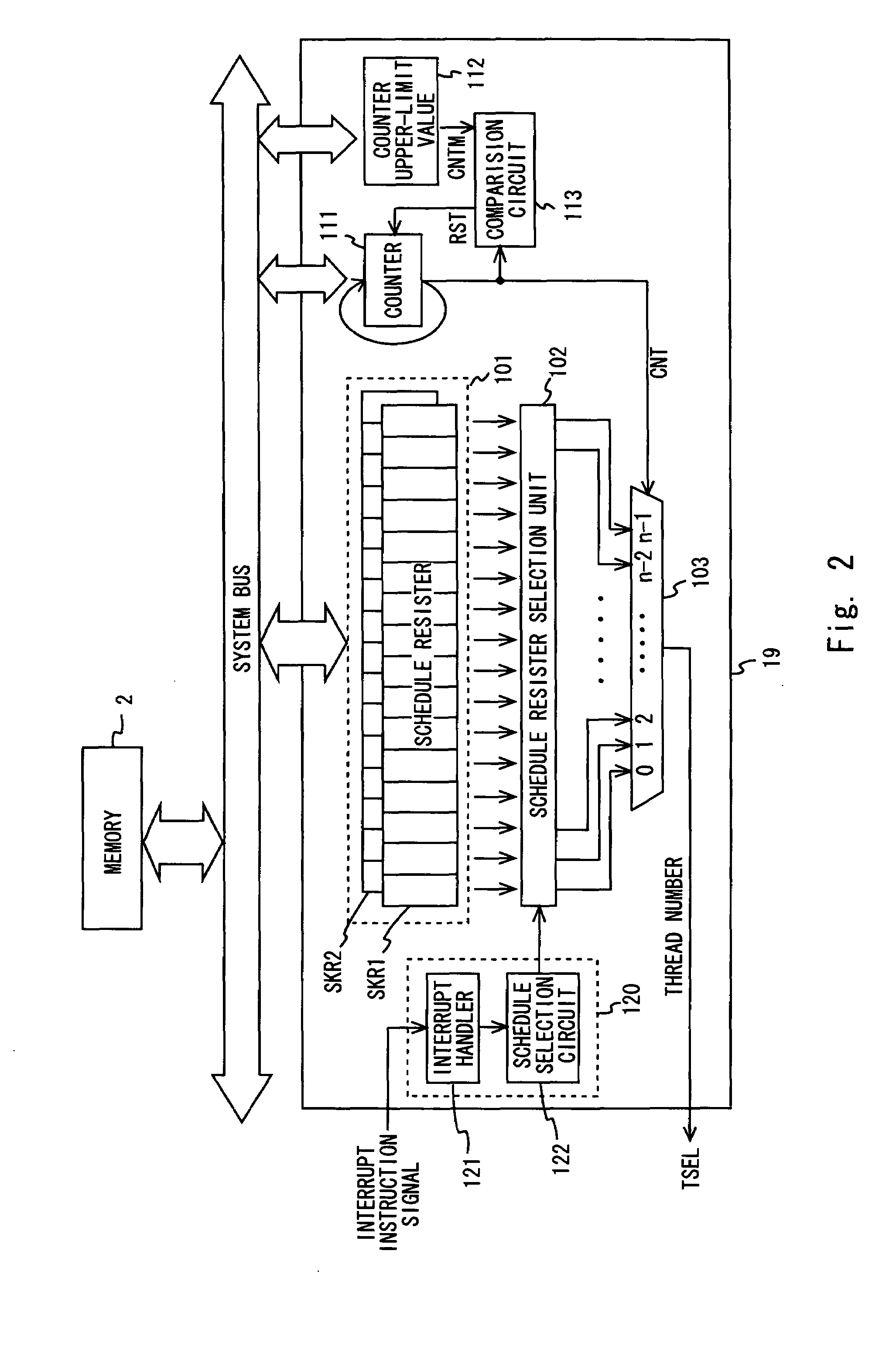
[0090]A specific third exemplary embodiment to which the present invention is applied is explained hereinafter in detail with reference to the drawings. FIG. 12 is a block diagram of a thread scheduler 19 in accordance with a third exemplary embodiment of the present invention. The third exemplary embodiment of the present invention is different from the first exemplary embodiment in that it has a normal scheduler 201 and the like as an additional scheduler. Further, each of the slots possessed by the thread schedule registers in the thread control resister unit 101 retains a flag that is used to generate a real-time bit signal in addition to the hardware thread number. Other configurations are same as those of the first exemplary embodiment. Therefore, the following explanation for this third exemplary embodiment of the present invention is made with a particular emphasis on the parts that are different from the first exemplary embodiment.

[0091]As ...


PUM


Abstract

In an exemplary aspect, the present invention provides a multi-thread processor including a plurality of hardware threads each of which generates an independent instruction flow, a thread scheduler that outputs a thread selection signal in accordance with a first or second schedule, the thread selection signal designating a hardware thread to be executed in a next execution cycle among the plurality of hardware threads, a first selector that selects one of the plurality of hardware threads according to the thread selection signal and outputs an instruction generated by the selected hardware thread, and an execution pipeline that executes an instruction output from the first selector, wherein when the multi-thread processor is in a first state, the thread scheduler selects the first schedule, and when the multi-thread processor is in a second state, the thread scheduler selects the second schedule.

Description

BACKGROUND[0001]1. Field of the Invention[0002]The present invention relates to a multi-thread processor.[0003]2. Description of Related Art[0004]In recent years, multi-thread processors have been proposed in order to improve the processing power of processors. A multi-thread processor has a plurality of threads each of which generates an independent instruction flow. Further, the multi-thread processor performs arithmetic processing while changing the instruction flow to be processed in the arithmetic circuit that processes instructions in pipeline processing between a plurality of instruction flows that are generated by the respective plurality of threads. At this point, the multi-thread processor can execute an instruction generated by one thread in one execution stage of the pipeline while executing an instruction generated by another thread in another execution stage. That is, in the arithmetic circuit of the multi-thread processor, instructions that are independent of each oth...

Claims


Application Information

Patent Timeline
Patent Type & Authority Patents(United States)
IPC IPC(8): G06F9/46
CPCG06F9/3836G06F9/3851G06F9/4893G06F9/3867Y02B60/144Y02D10/00
Inventor ADACHI, KOJIMATSUNAGA, TOSHIYUKI
Owner RENESAS ELECTRONICS CORP
Learn More