Ocean wave energy converter

a technology of energy converter and ocean wave, which is applied in the direction of electric generator control, machines/engines, mechanical equipment, etc., can solve the problems of very small buoyancy volume to move up a wave, difficult to produce commercial levels of consistent electricity, and difficult to extract energy

Inactive Publication Date: 2013-09-17
PERPETUWAVE POWER
View PDF11 Cites 12 Cited by
  • Summary
  • Abstract
  • Description
  • Claims
  • Application Information

AI Technical Summary

Benefits of technology

This invention is for a device that can capture energy from ocean waves. It consists of many small floats that move up and down as waves pass over them. These floats are attached to arms that are attached to a structure above the water. The movement of the floats creates energy that can be turned into useful energy. The device is designed to work well in extreme conditions with high wave heights. It is efficient and can be raised for maintenance without affecting other floats. The guidance arms make the floats move in a way that increases energy capture.

Problems solved by technology

Designing a successful ocean wave converter or power plant is complex, and for over a hundred years, a large number of different designs have been trialled but still none are in commercial production and none have proved beyond doubt via the public release of actual performance levels (which is the standard in the established wind turbine and solar industries) that the design can make commercial levels of power output let alone at an acceptable cost.
The reality is there is a limited amount of energy in the oceans waves with average wave height of about 1 meter prevalent in most oceans of the world, and the energy is very difficult to extract being a pulsing type energy available about every ten seconds being an average wave period, and some 50+ meters between consecutive waves.
This makes it extremely difficult to produce commercial levels of consistent electricity and for a design to be successful in this environment requires a very specific design that is tailored to the energy source.
U.S. Pat. No. 1,925,742 discloses a single trailing arm which has a float thereto affixed and as such the design is very low in power production and has a very small buoyancy volume to move up a wave.
The small buoyancy volume offered by the cylindrical floats and the large distance between the floats is inefficient at extracting energy from the waves and again results in low performance per square meter of the energy converter.
U.S. Pat. No. 4,560,884 discloses two trailing arms pivotally attached to each elongate, independently operated float but the floats are too small and are spaced too far apart for the wave energy converter to make sufficient power for each square meter of energy converter, and thus again the design has a low power output and is not economical.
It is suggested that the above prior art does not individually or in combination provide the right mix of features required to produce a high energy density or acceptable cost ocean wave power energy converter.

Method used


Image

  • Ocean wave energy converter
  • Ocean wave energy converter
  • Ocean wave energy converter

Examples


Embodiment Construction

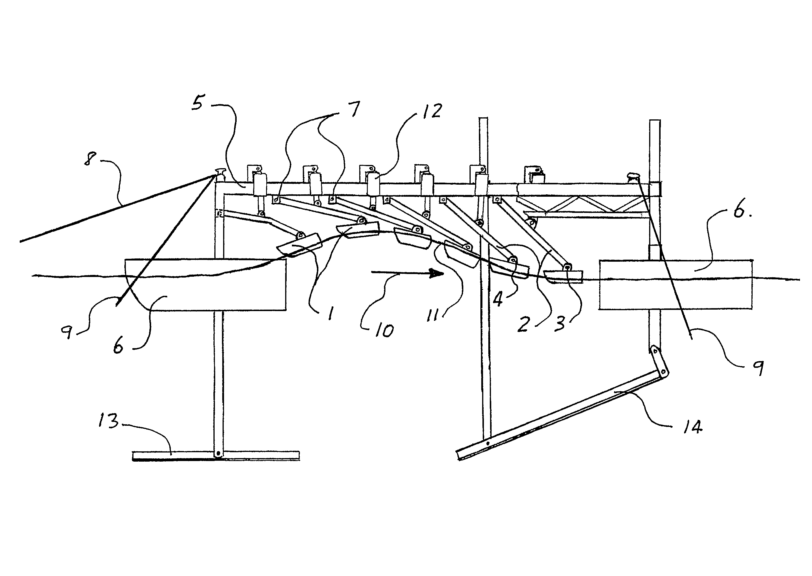
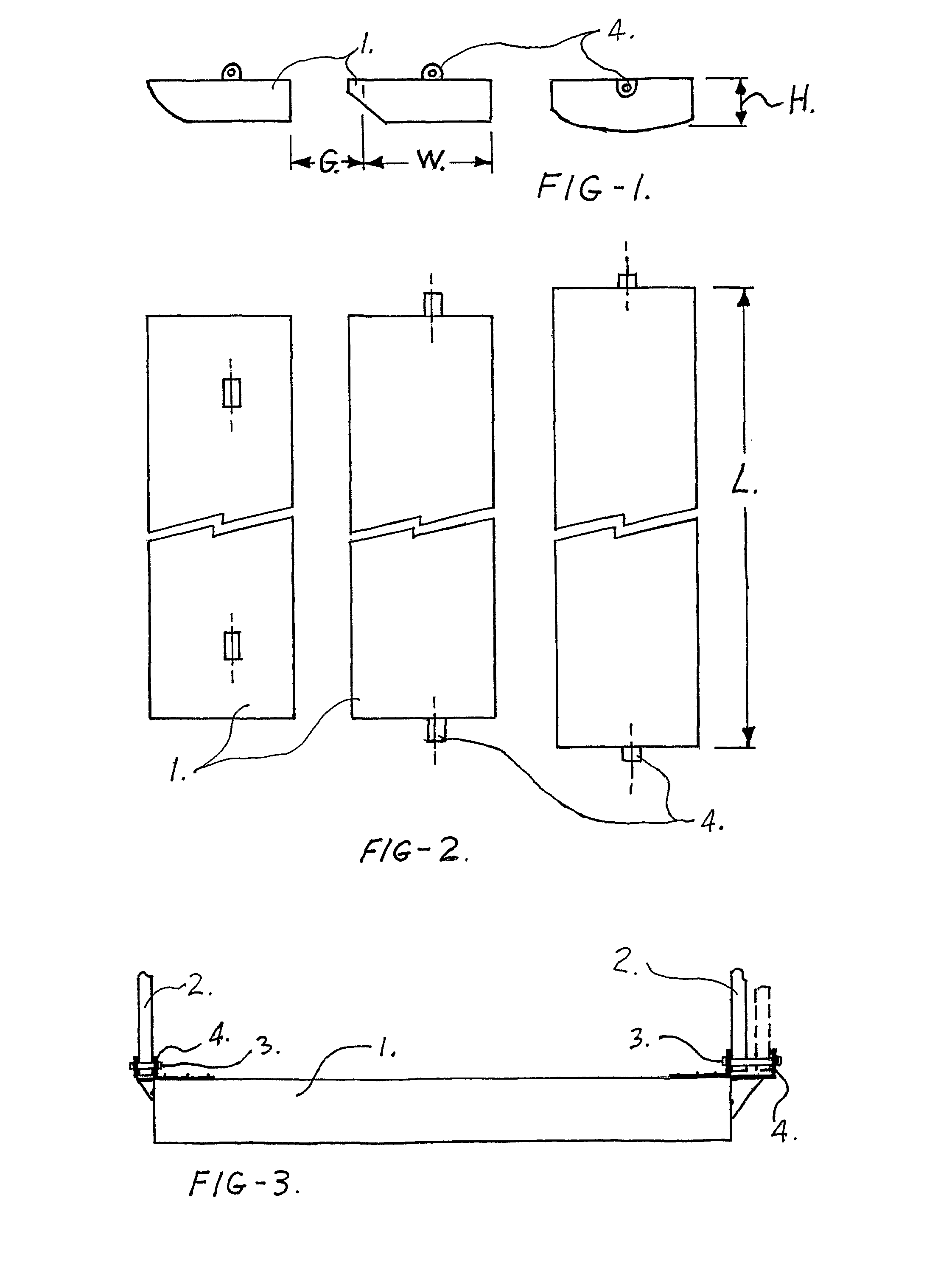
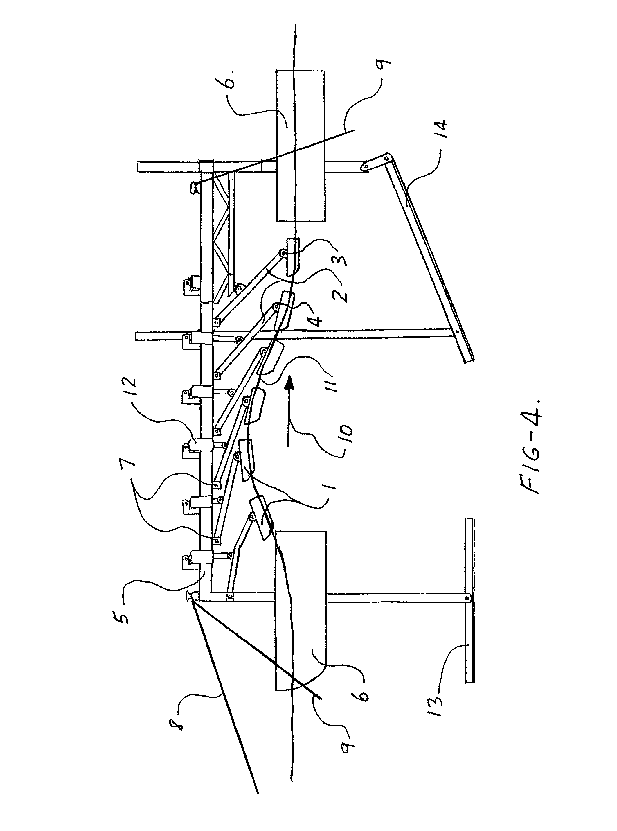
[0025]The improved ocean wave energy converter illustrated in FIGS. 1 and 2 includes an array of floats 1 that illustrate some of the possible combinations of shape of the float and guidance arm float bracket 4. The length (L) of the floats is about 600% of the width (W) of the float. The float on the left in FIGS. 1 and 2 is the forward float of the array and has a rectangular back section and an elliptical front lower section with the guidance arm float brackets located in from the end of the float as shown. The float has a rectangular rear section and an angled front section for eighty percent of the height of the front side as shown on an angle of 50° from the top. On the float on the left and the float in the middle of FIGS. 1 and 2, the guidance arm float bracket 4 is wider than the width of the guidance arm so the guidance arm may slide sideways relative to the float. In the float on the right hand side of FIGS. 1 and 2, the float has a rectangular section on the top and the ...


PUM


Abstract

An ocean wave energy converter comprising a structure that is supported above the water and that has means to stabilize the structure, an array of guided independently operated elongate floats that operate from the structure above via two or more guidance arms, wherein each guidance arm is attached to the structure so that the floats pivot about the horizontal axis parallel the length of the floats, each float is attached to the guidance arms at the center of buoyancy of the float, and the floats are substantially parallel to the wave fronts.

Description

CROSS REFERENCE TO RELATED APPLICATIONS[0001]This application claims priority to PCT application No. PCT / AU2009 / 000611, filed May 15, 2009, which claims priority to Australian patent application No. 2008902409, filed May 15, 2008, both of which are incorporated herein by reference.TECHNICAL FIELD[0002]This invention relates to an improved ocean wave energy converter. This invention has particular application to an improved ocean wave energy converter which uses oscillating or reciprocating motion of a number of independently operated elongate floats to produce electrical or other forms of useful energy. Other forms of useful energy include, for example, hydraulic energy for powering desalination plant, pumping plant or such like. The floats are guided by two or more guidance arms for each float.BACKGROUND ART[0003]Designing a successful ocean wave converter or power plant is complex, and for over a hundred years, a large number of different designs have been trialled but still none ...

Claims


Application Information

Patent Timeline
Patent Type & Authority Patents(United States)
IPC IPC(8): F03B13/10F03B13/12H02P9/04
CPCF03B13/1815F03B13/20Y02E10/38F05B2240/93Y02E10/30
Inventor DULLAWAY, GLEN
Owner PERPETUWAVE POWER
Why Eureka
Try Eureka